
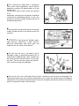
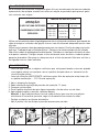
• OPERATING INSTRUCTIONS
• MODE D’EMPLOI
• BEDIENUNGSANLEITUNG
• INSTRUCCIONES PARA EL USO
• MANUAL DE INSTRUÇÕES
• ИНСТРУКЦИЯ ПО ЭКСПЛУАТАЦИИ
• LIBRETTO ISTRUZIONI
• DO NOT USE THE MACHINE WITHOUT FIRST READING THE OPERATING INSTRUCTIONS
• N’UTILISER L’APPAREIL QU’APRÈS AVOIR LU LE MANUEL D’INSTRUCTIONS
• GERAT ERST NACH LESEN DER BEDIENUNGSANLEITUNG VERWENDEN
• NO UTILISE EL APARATO SIN LEER ANTES LAS INSTRUCCIONES PARA SU USO
• NÃO USE A MÁQUINA SEM LER A MANUAL DE INSTRUÇÕES
•• НЕ ИСПОЛЬЗУЙТЕ УСТРОЙСТВО, НЕ ПРОЧИТАВ СНАЧАЛА ИНСТРУКЦИЮ ПО ЭКСПЛУАТАЦИИ
• NON USARE LA MACCHINA SENZA AVERE LETTO LE ISTRUZIONI PER L’USO
BBOOXXJJEETT
TURBO 8.70
TURBO 8.90
TURBO 11.50
TURBO 15
TURBO 19
TURBO 21


1
INDEX
ENGLISH............................................................................................ pag.
FRANÇAIS....................................................................................... pag.
DEUTSCH......................................................................................... pag.
ESPAÑOL........................................................................................... pag.
PORTUGUÉS................................................................................ pag.
РУССКИЙ......................................................................................... стр..
ITALIANO........................................................................................... pag.
PART LIST........................................................................................ pag.
LISTE DE PIÈCES DÉTACHÉES........................... pag.
ERSATZTEILLISTE................................................................. pag.
LISTA DE REPUESTOS.................................................... pag.
LISTA DE PEÇAS DE REPOSIÇAO................... pag.
ВЕДОМОСТЬ ЗАПАСНЫХ ЧАСТЕЙ
........... pag.
NOMENCLATURA RICAMBI..................................... pag.
OPTIONALS......................................................................... pag.
4
20
36
52
68
84
100
117
117
117
117
117
117
117
128-129

2
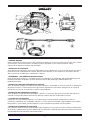
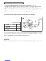
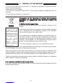
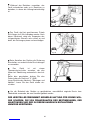
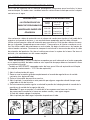
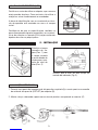
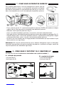
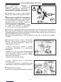
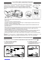
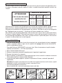
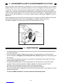
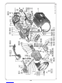
• CONTROL DEVICES
Before connecting the machine to the water and electrical supplies, it is necessary to know the function of the controls
on the machine. This must be done in accordance with the descriptions in the Instruction Manual, taking
reference to the relevant instructions and illustrations.
• DISPOSITIFS DE CONTRÔLE
Avant de brancher l’appareil sur les réseaux d’alimentation d’eau et d’électricité, il est nécessaire de bien connaître le
fonctionnement de ses dispositifs de contrôle. Effectuer cette opération en vous référant aux instructions données
dans ce manuel et aux indications et illustrations y relatives.
• BEDIENUNGS - UND KONTROLLVORRICHTUNGEN
Bevor Sie das Gerät mit Wasser - und Stromanschlüssen verbinden ist es notwending, daß Sie die Bedienungs-und
Kontrollvorrichtungen des Gerätes verstehen. Bitte lesen Sie die Beschreibungen und Illustrationen der
Bedienungsanleitung.
• DISPOSITIVOS DE PUESTA EN MARCHA Y CONTROL
Antes de conectar el equipo a las redes de alimentación de agua y electricidad, es necesario conocer sus dispositivos
de puesta en marcha y control. Efectuar estas operaciones siguiendo las indicaciones que figuran en el manual de
istrucciones así como de sus ilustraciones grafícas correspondientes.
• DISPOSITIVO DE COMANDO E CONTROLO
Antes da ligação às redes de alimentação hídrica e eléctrica, é necessário saber qual a função dos dispositivos de
comando e controlo da máquina. Efectuar esta operação conforme descrito no Manual de Instruções.
• УСТРОЙСТВА УПРАВЛЕНИЯ
Перед тем, как подсоединить изделие к источникам воды и электроэнергии, необходимо изучить его
устройства управления. Это необходимо сделать в соответствии с описаниями, содержащимися в настоящей
Инструкции по экплуатации, уделяя внимание соответствующим инструкциям и иллюстрациям.
• DISPOSITIVI DI COMANDO E CONTROLLO
Prima dell’allacciamento alla rete di alimentazione idrica ed elettrica è necessario conoscere la funzione dei dispositivi
di comando e controllo della macchina. Effettuare questa operazione seguendo quanto descritto nel Manuale Istruzioni
facendo riferimento alle indicazioni e illustrazioni relative.
BB
BBOO
OOXX
XXJJ
JJEE
EETT
TT

3
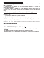
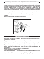
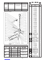
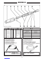
STANDARD EQUIPMENT
Inlet hose connection with water filter (INLET)
High pressure hose connection (OUTLET)
Pressure adjusting knob
Pressure indicator
ON/OFF switch
Chemical regulator (CHEM)
Chemical filter
Oil dipstick
Oil level indicator
Automatic gun
“QUICK-LANCE”
ROTOTEK (or “MULTIREG”)
High pressure hose
Safety lock
ÉQUIPEMENT STANDARD
Raccord d’alimentation eau et filtre (INLET)
Raccord de tuyau haute pression (OUTLET)
Bouton de régulation de la pression
Indicateur de pression
Interrupteur Marche/Arrêt
Molette de dosage du détérgent (CHEM)
Crépine du détérgent
Jauge de remplissage d’huile
Voyant du niveau d’huile
Pistolet automatique de sécurité
Lance à raccordement rapide “QUICK-LANCE”
ROTOTEK (ou “MULTIREG”)
Tuyau haute pression
Cran de sûreté
STANDARDAUSRÜSTUNG
Wasser-Anschluß mit Filter (INLET)
Hochdruck-Ausgang (OUTLET)
Druckregel-Griff
Druckanzeiger
EIN/AUS Schalter
Chemie-Dosierung (CHEM)
Chemie-filter
Ölmeßstab
Ölstandsanzeige
Spritzpistole
Wechsel-Lanze “QUICK-LANCE”
ROTOTEK (oder “MULTIREG”)
Hochdruckschlauch
Sicherheitssperre
EQUIPO STANDARD
Entrada + filtro agua (INLET)
Salida (OUTLET)
Mando de regulación de la presión
Manómetro
Interruptor
Mando de regul. del detergente (CHEM)
Filtro del detergente
Tapón de aceite con varilla de nivel
Mirilla nível de aceite
Pistola automática
Lanza “QUICK-LANCE”
ROTOTEK (o “MULTIREG”)
Tubo de alta presión
Seguro
EQUIPAMENTO STANDARD
Entrada de água com filtro (INLET)
Conector de saída de alta pressão (OUTLET)
Manípulo de ajuste de pressão
Indicador de pressão
Interruptor líg/des (ON/OFF)
Regulador de detergente (CHEM)
Filtro de aspiração de detergente
Tampa de óleo
Indicador de nivel de óleo
Pistóla automática
Lança
ROTOTEK (ou “MULTIREG”)
Mangueira de alta pressão
Travão
EQUIPAGGIAMENTO STANDARD
Entrata + filtro acqua (INLET)
Uscita (OUTLET)
Manopola di regolazione della pressione
Manometro
Interruttore
Pomolo di regolazione del detersivo (CHEM.)
Filtro detersivo
Tappo carico olio con asta di controllo
Spia livello olio
Pistola automatica
Lancia “QUICK-LANCE”
ROTOTEK (o “MULTIREG”)
Tubo alta pressione
Sicura
СТАНДАРТНОЕ ОБОРУДОВАНИЕ
Вход + Водяной фильтр
Выход (OUTLET)
Регулятор давления
Манометр
Выключатель
Регулировка моющего средства (CHEM)
Фильтр моющего средства
Пробка для заливки масла со стеклом для контроля
Индикатор уровня масла
Пистолет
Гидромонитор
Rototek или Multireg 99
Шланг высокого давления
Предохранитель

4
TABLE OF CONTENTS
1 - Description of symbols on the high pressure cleaner....................................... 5
2 - Technical specifications of the BOXJET............................................................ 6
3 - Product use....................................................................................................... 7
3.1 • Designated use................................................................................... 7
4 - Preliminary operations....................................................................................... 7
4.1 • Unpacking........................................................................................... 7
4.2 • Identification label............................................................................... 8
5 - Installation......................................................................................................... 8
5.1 • Connection high pressure outlet......................................................... 8
5.2 • Connection to water supply................................................................ 9
5.3 • Connection to electric system............................................................ 10
5.3.1 • Cut-out switch (Only the United States).......................................... 10
5.4 • Use of extention cord......................................................................... 11
5.5 • Start-up............................................................................................... 11
6 - General warnings.............................................................................................. 12
7 - Chemical product use....................................................................................... 15
8 - Use of "ROTOTEK" or "MULTIREG 99"............................................................ 15
9 - Precautions againt freezing, and instructions for storage.................................... 16
10 - Maintenance...................................................................................................... 16
10.1 • Oil change......................................................................................... 17
10.2 • Inlet filter............................................................................................ 17
10.3 • Replacement of high pressure nozzle ..............................................17
11 - Machine scrapping............................................................................................ 18
12 - Trouble shooting............................................................................................... 19
ENGLISH

5
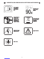
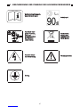
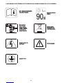
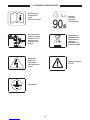
1 - DESCRIPTION OF SYMBOLS ON THE HIGH PRESSURE CLEANER
DDoo nnoott ddiirreecctt tthhee jjeett
aaggaaiinnsstt ppeerrssoonnss oorr
aanniimmaallssppoowweerr oouutt--
lleettss oorr tthhee mmaacchhiinnee
iittsseellff..
WWaarrnniinngg!! RRiissk
k ooff
eelleeccttrrooccuuttiioonn
GGrroouunnddiinngg
SSppeecciiaall wwaassttee.. DDoo
nnoott ddiissppoossee ooff tthhiiss
pprroodduucctt iinn nnoorrmmaall
hhoouusseehhoolldd ggaarrbbaag
gee
WWaarrnniinngg ssiiggnn
RReeaadd tthhee iinnssttrruuccttiioonn
mmaannuuaall bbeeffoorree uussee..GGaarraanntteedd ssoouunndd
ppoowweerr lleevveell..

6
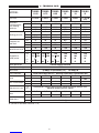
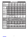
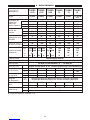
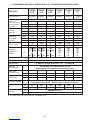
2 - TECHNICAL DATA
MODEL
Singlephase
motor power
kW.
Motor protection
Motor protection grade
°C
m/sec2Fixed nozzle A(8) than 2,5 - Rotating nozzle A(8) 3 (uncertainly 0,5)
Max. water inlet
temp °F
m
Max suction depth ft
High pressure hose Thermoplastic material reinforced with nylon braid internal diameter 5/16”
Maximum working pressure 130 bar
Mass
Dimensions mm
inches
Noise level*
Lance vibration*
P.S.I.
Overpressure
peak limit
Recoil thrust of jet N
Flow rate
E.W. bar / MPa / P.S.I.: specific jet pressure in bar / MPa / P.S.I.
Equivalent
washing impact
with rotating
nozzle jet
E.W. MPa
E.W. P.S.I.
Working pressure
MPa
E.W. bar
bar
P.S.I.
MPa
bar
*(Reference Standard EN60335-2-79)
8 m
26 ft
TURBO
21
TURBO
11-50
TURBO
8-70
TURBO
8-90
TURBO
15
TURBO
19
11 l/min. 8 l/min. 8 l/min. 8 l/min. 8 l/min. 2.11 G.P.M.
(USA)
10 14.5 16 12 13 13.8
100 145 160 120 130 138
1450 2100 2320 1750 1885 2000
50 70 90 55 60 70
57 9 5.5 6 7
725 1015 1300 800 870 1015
80 100 120 85 90 100
810 12 8.5 910
1160 1450 1750 1235 1300 1450
20 < 20
Current thermal overload
IPX5
Lp dB(A) 76 (uncertainly 1,5) - Lw dB(A) 90
60
11111
3.3
360x240x235 (h)
14.2x9.4x9.2 (h)
Kg 2< 2
20
2
< 20
< 2
< 20
< 2
< 20
< 2
V.
Hz.
A.
1,68 1,64 1,68 1,64 1,86 1,36 1,40 1,58
230
8,2
240
8
50
230
8,2
240
8
50
230
8,6
240
8,4
50
100
50
15
100
60
15
115
60
15
140
60 60 60 60
Kg
lbs
18,5 18,5 18,7 18,6 19,4
42.8

7
WE CONGRATULATE YOU on your choice that shows your level of technical knowledge and
love of beautiful objects.
In fact, you have purchased a highly technological machine produced by the world's
largest manufacturer of high pressure cleaner pumps.
This machine is so useful and versatile that you will use it for many years.
THIS BOOKLET IS AN INTEGRAL PART OF YOUR MACHINE AND SHOULD BE
CAREFULLY READ BEFORE PROCEEDING WITH INSTALLATION, START-UP AND
USE.
This booklet contains important safety information and instructions for use and maintenance
of the high pressure cleaners BOXJET and should be kept in a safe place.
3. PRODUCT USE
The machine is exclusively designed for washing, by way of a pressurized water jet, objects,
things or any surface suitable for cleaning by a pressurized water jet with the possibility of
adding liquid detergent.
ATTENTION: this appliance was designed for use of detergents recommended by the manu-
facturer. The use of other chemical products may jeopardize the safety of the appliance itself.
The liquid detergent additives must be chosen in consideration of the chemical compatibility
with the components of the pump and of the surface to be cleaned.
IMPORTANT: use only detergents that are biodegradable, and in any case complying with the
regulations applicable in the country where they are used.
3.1 DESIGNATED USE
4. PRELIMINARY OPERATIONS
4.1 UNPACKING
Unpack and make sure that the machine is complete and undamaged.
If the machine appears damaged in any way, do not use the machine and consult our dealer.
For shipping reasons some parts may be included separately. In this case assemble parts as
indicated in this booklet.
Keep all packaging materials (bags, boxes, tape) out of reach of children.
THE DESTINATION OF USE OF THIS MACHINE MUST BE STRICTLY ADHERED TO. ANY
OTHER USE MUST BE CONSIDERED AS INCORRECT.
THE MANUFACTURER CANNOT BE HELD RESPONSIBLE FOR DAMAGES CAUSED BY
INCORRECT USE OF THE MACHINE.
THE MACHINE MUST NOT BE TAMPERED WITH FOR ANY REASON. IN CASES OF
TAMPERING THE MANUFACTURER DECLINES ANY RESPONSABILITY ON THE FUNC-
TIONING AND SAFETY OF THE MACHINE.
IT IS FORBIDDEN TO STORE OR USE THE UNIT IN ENVIRONMENTS WITH POTEN-
TIALLY EXPLOSIVE ATMOSPHERE.

8
Before using this machine make sure that it has an ID
label. If it is without, do not use the machine and
consult your dealer immediately.
The identification label with technical specifications
is placed on the trolley and is always visible.
Check that ID label specifications correspond to
those required and that the power characteristics
for the outlet (V/Hz) are those shown on the label.
4.2 - ID LABEL
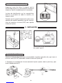
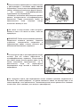
5 - INSTALLATION
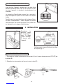
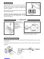
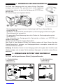
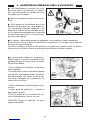
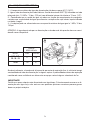
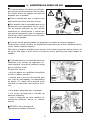
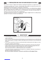
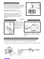
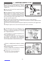
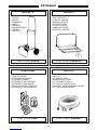
5.1 HIGH PRESSURE CONNECTION
Replace the red
travel plug (fig.1)
with the vented
black/yellow
dipstick provided
(fig.2).
Check that the oil in the sight glass is at
the half-way level (fig.3).
1- Connect one end of the high pressure hose to the gun (A) and the other to the outlet con-
nection (B).
2- Assemble the lance by pushing the two halves together and then fix by turning the connec-
tor (C).

9
5.2 - CONNECTION TO THE WATER SUPPLY
1- The maximum temperature of the inlet water must not exceed 60°C (140°F).
2- Connect the water supply to the INLET port (D) by means of a reinforced hose (minimum
1,5 MPa - 15 bar - 200 psi) with internal diameter of no less than 13 mm. (1/2").
3- Since the water flow decreases according to the length of the hose, make sure that the quan-
tity of water supplied to the machine is not less than the quantities indicated in the chart
below.
4- The pressure of the inlet water must not exceed 1 MPa, 10 bar, 145 psi.
ATTENTION: The water supply which enters into the washer is not drinkable.
IMPORTANT
The water supplied to the machine must be clean. Running the unit without water, or with water
which is dirty, contains grit or corrosive liquids, causes serious damage to the machine.
If the user wishes to power the washer by means of free suction, simply emerge the end of the
supply tube in the water to be suctioned. The maximum suction depth considered as the dis-
tance in height between the water surface and the pump is 1m.
D
8•90 - 8•70
15 - 19 - 21
MODEL L/min. G.P.M. USA
11
15
2.9
4
11•50
FLOW RATE OF
WATER SUPPLY

10
5.3 - CONNECTION TO ELECTRICAL SYSTEM
1 - Check that the voltage of the electrical system (mains) is the same as indicated on the ID
label of the machine.
2 - Check that the plug complies with local safety regulations, and that it is provided with
ground connection (earth).
3 - Ensure that the outlet is protected by a "cut-out" (differential magnetic-thermal switch with
sensitivity of less than 30mA per 30ms) or that a device is present which can test the earthing
circuit.
4 - Do not connect other appliances to the same power outlet while using the machine.
5 - Insert the plug only after checking that the machine switch is in the OFF position.
6 - The standard plug for 50 Hz versions: SCHUKO 250V - 16A, standard CEE7-VII
DIN49441-2-AR2.
7- Fully unwind the power cord to prevent overheating.
8 - Do not crush on the power cord.
9 - Do not use the high pressure cleaner if the electric cable is damaged.
10 - If the power cord is damaged, its replacement can be effected only by the technical ser-
vice personnel or by a qualified technician.
WARNING: IN CASE OF POWER FAILURE DURING OPERATION TURN OFF THE
UNIT FOR SAFETY REASONS.
5.3.1 - CUT-OUT SWITCH (Only the United States)
This UL version high-pressure washer is equipped with a cut-out switch contained in the power
cable plug.
Said equipment provides extra protection against the risk of electric shock.
When replacing the plug or cable, use the same components including the cut-out device.

11
5.4 - USE OF CORDS
If an extension cord is used, make sure that plug and receptacle are of a water-tight type. In
any case they must be raised from the ground in order to avoid possible contact with water.
Use only extension cables with the same number of conductors as those of the machine cable,
including the earthing cable, and with a suitable plug/socket for the cable used.
Only use extension cords for outdoor use. Said type of cable is marked "Suitable for outdoor
use." Store inside when not in use.
Do not use damaged extension cords. Cables should not be located near sources of heat or
sharp edges. Always disconnect the plug from the socket before removing the extension cord
from the product. Do not pull the cable to pull the plug out of the outlet. Do not touch the plug
or connections with wet hands.
WARNING
USE OF INADEQUATE
EXTENSION CORDS
MAY CAUSE SAFETY
HAZARDS
SELECTION TABLE
Voltage
220÷240
220÷240
100÷115
100÷115
Extension
cord length
Cord section
mm2
Up to 20 m
From 20 to 50 m
Up to 20 m
From 20 to 50 m
1,5
2,5
2,5
4
5.5 - START-UP
- Before starting up and using the machine, make sure that it is positioned on the ground or
leaning against a stable support and that the resting surface is level or with a minimum slope.
- It is ESSENTIAL to ensure that the suction filter is clean before use. (see maintenance chap-
ter – 10.2 inlet filter).
1- Open water supply
2- Set the pressure to zero by turning the knob anti-clockwise.
3- Switch on the unit.
4- Hold the gun in the open position for a few seconds to allow the air to escape from hoses.
5- At this point adjust the machine to your pressure requirements and you are ready to enjoy
your work.
Attention! The water pressure at the outlet of the lance generates a force on itself;
therefore, grip the lance with both hands and with a secure grip.
- Switch off the machine when work is completed.
- Open the gun to release pressure still in the hose.

12
6 - GENERAL WARNINGS
High pressure cleaners can be used neither
by children nor by non authorized persons.
Children must be supervised to prevent them
from playing with the machine.
Keep this machine out of reach of children
at all times.
This equipment was not designed to be used
by persons with reduced physical, sensorial or
mental capabilities, or with limited experience
or knowledge, unless a person responsible for
their safety provides them with supervision or
the instructions for the use of the equipment.
NO
Only operate the machine in safety condi-
tions, avoiding any potentially dangerous
situation for the user and others. The machine
operator should:
• Avoid to operate the machine on unbalanced
surfaces;
• Remember that the high pressure water jet
causes a recoil effect on the pistol. The recoil
values are indicated in the technical specifica-
tions table;
• Use protective clothing.
• Wear protective goggles and rubber slip-
proof boots
• Avoid dispersing substances that are pollut-
ing, toxic or harmful in any way.
ATTENTION: Risk of explosion. Do not spray
flammable liquids.
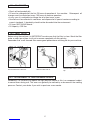
The high pressure water jet may be dangerous if used incorrectly. Never direct the jet at per-
sons and/or animals, electrical appliances or the machine itself. Do not use the machine when
persons and/or animal are within the range of its high pressure jet.
Do not direct the jet against yourself or other persons to clean clothes or shoes.
NO
NO

13
This machine has been built in conformity
with current safety regulations. Use of electric
appliances requires the observations of a few
simple rules:
Do not touch electric parts when the machine
is on.
Inspection, maintenance and repairs should be
carried out by qualified personnel. In any case
unplug the machine before performing any of
the above operations.
Do not pull the cord to disconnect the power
supply and do not pull on the hose to move the
machine.
ATTENTION: high pressure flexible hoses,
high pressure connectors, safety devices,
electrical connections and spray guns are
important for the safety of the device.
Do not start the unit if the power cord is
damaged. Apply to qualified personnel for its
replacement. Replacement cords should have
the same technical specifications as the origi-
nal cord. Do not carry out repairs on the elec-
trical cord and avoid cord damage.
Do not start the unit if the high pressure hose, connectors and the gun are damaged. By
replacement make sure that the new components have at least the same rating as the original
components.The technical specifications of the hose should be printed on the hose itself (max
pressure, production date, manufacturer).
NO
NO
NO

14
Avoid covering the machine during use and
use the machine in a well ventilated area.
When the machine is off insert the safety
device on the gun to avoid accidental opening.
The unit is equipped with a thermal protec-
tor which trips and electrically disconnects the
motor when it overheats.
If this event occurs, turn the selection knob on
the unit to the "0" position (machine OFF).
Read carefully the troubleshooting guide befo-
re starting the unit again.
To ensure the security of the machine, use only original spare parts and accessories supplied
by the manufacturer.
THE MANUFACTURER CANNOT BE HELD RESPONSABLE FOR ANY DAM-
AGE CAUSED BY DISRESPECTING THE DESIGNATED USES OF THIS
MACHINE, IT'S INSTRUCTIONS AND WARNINGS INDICATED IN THIS
BOOKLET.
NO
NO
Do not leave the machine running for more
than 5 minutes with the gun closed. After this
time period the water temperature within the
machine increase and may cause damage to
the machine.

15
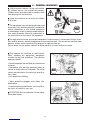
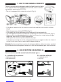
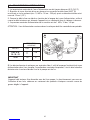
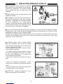
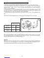
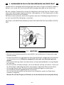
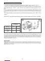
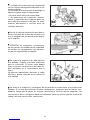
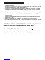
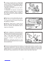
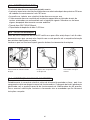
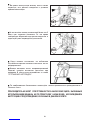
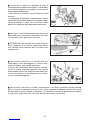
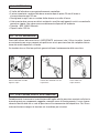
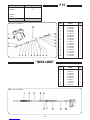
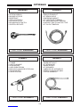
7 - HOW TO USE CHEMICAL PRODUCTS
The unit can suck and mix detergents and other liquid chemicals thanks
to an automatic device incorporated in the unit itself, which is remote
controlled by operating the ROTOTEK.
- The unit is equipped with a chemical suction kit (Fig. A).
- Fit the brass connector into the chemical control knob and filter into chemical container
(Fig.B).
- Select low pressure with the ROTOTEK (Fig. C).
- At this point the suction and mixing of the chemical will start automatically.
- You can regulate the quantity of chemicals by adjusting the chemical control knob (Fig. D).
- When you wish to stop using chemicals in order to clean on rinse, simply release the gun
trigger and adjust the ROTOTEK to high pressure.
At this point the chemical injection automatically stops.
If you foresee not using the unit for a long period of time, we suggest to clean the chemical
suction kit with clear water to avoid chemical deposit build-up.
Attention! In the event of direct contact with detergent additives, follow instructions provided
by the manufacturer and/or product retailer and rinse the affected body part with clean water.
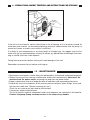
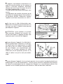
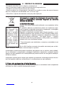
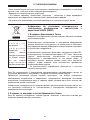
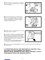
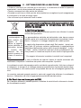
8 - USE OF ROTOTEK OR MULTIREG 99
Pressure selection must be carried out with closed gun (1)
A - selection of the pressure
• High pressure (2)
• Low pressure (3)
B - selection of the jet
• straight pin jet (4)
• fan jet (5)
OFF
2
1
3
HL
HL
4
5
HL
HL
AB

16
9 - PRECAUTIONS AGAINST FREEZING AND INSTRUCTIONS FOR STORAGE
10 - MAINTENANCE
• Maintenance and repairs should always be performed by trained and authorised personnel.
• Before carrying out any cleaning, maintenance and/or parts replacement, disconnect the
machine from the power mains, removing the plug from the power outlet.
• Proper maintenance favours a longer duration of operation and improved performance.
• Periodically check the conditions of the washer, pressurised parts (pipe, fittings, lance) and
the electrical cable (see "General warnings for use").
Check for any water or oil leaks and/or malfunctions.
If necessary, replace affected parts.
The list of specific machine components and circuit diagrams are contained in this booklet.
Contact Interpump Group customer service in the event of any doubts.
If the unit is to be stored in a place where there is risk of freezing, or it is to remain unused for
more than three months, we recommend placing some anti-freeze solution into the pump, (a
normal anti-freeze as used in your vehicle is sufficient).
If in doubt at low temperatures or any long length of storage time, we suggest you turn the
motor with the key provided before starting, to release any possibilities of blockages from free-
zing or a build up of lime scale deposits.
Taking these precautions before starting will avoid damage to the unit.
Remember to remove the key before switching on.

17
• Check oil level periodically.
• Oil must be changed after the first 20 hours of operation of the machine. Subsequent oil
changes must be carried out every 150 hours of machine operation.
• In any case it is advisable to change the oil at least once a year.
• Used oil must be collected in containers and disposed of in special centres according to
current standards. It absolutely should not be discarded into the environment.
• Oil type: SAE 15W40 Mineral.
• Oil capacity: 0,33 liter.
10.1 - OIL CHANGE
10.3 - REPLACEMENT OF HIGH PRESSURE NOZZLE
Periodically it is necessary to replace the high pressure nozzle as this is a component subject
to normal wear during use. This wear can generally be noticed by a decrease of the working
pressure. Contact your dealer if you wish to purchase a new nozzle.
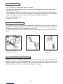
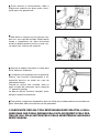
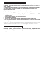
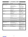
10.2 - INLET FILTER
Before using the machine it is IMPORTANT to make sure that the filter is clean. Wash the filter
under a water tap or blow it with air to remove completely all dirt particles.
Remember that a well-cleaned filter means good performance and long life for your machine.
Blow the filter with air.
Remove filter from water inlet. Wash the filter under a water
tap.

11 - DISPOSAL OF THE MACHINE
• In case of no further use of the machine, it is advisable to disconnect the power cord mak-
ing the machine inoperative.
• Keep out of reach of children.
• This machine is considered "special waste", disassemble and gather homogeneous parts for
recycling.
• Do not used recycled parts as spare parts.
IInnffoorrmmaattiioonn oonn tthhee ddiissppoossaall ooff eelleeccttrriicc aanndd eelleeccttrroonniicc
eeqquuiippmmeenntt iinn ccoommpplliiaannccee wwiitthh ddiirreeccttiivvee 22000022//9966 CCEE
((RRAAEEEE))..
11.. WWiitthhiinn tthhee EEuurrooppeeaann UUnniioonn
Warning: do not use the normal house trash bin to dispose of this
product.
Used electric and electronic equipment must be handled separately
and in compliance with the regulations relating to the treatment,
recovery and recycling of the said products.
In accordance with the regulations applied in the member States, pri-
vate users resident in the EU can take used electric and electronic
equipment free of charge to designated collection centers*. In some
countries * the local dealer, too, can withdraw the old product free of
charge if the user purchases a new, similar product.
* For more information contact your local campetent authorities.
If you experience difficulties in locating an authorized disposal center,
consult the dealer from whom you purchased the product.
The correct disposal of this product will contribute to ensure that the waste is submitted to the
required treatment, recovery and recycling, preventing the potential negative impact on envi-
ronment and human health, which could be caused by an unsuitable disposal of the waste.
The national regulations provide sanctions against whoever unlawfully disposes of or abandons
waste of electric or electronic equipment.
22.. IInn ccoouunnttrriieess oouuttssiiddee tthhee EEuurrooppeeaann UUnniioonn..
If you wish to dispose of this product, contact your local authorities to get information about the
correct disposal method.
Warning: the product
is marked with this
symbol, which means
that electric and elec-
tronic products should
not be disposed of
with the normal
house-hold waste. A
separate collection
system is foreseen for
these products.
18
A página está carregando...
A página está carregando...
A página está carregando...
A página está carregando...
A página está carregando...
A página está carregando...
A página está carregando...
A página está carregando...
A página está carregando...
A página está carregando...
A página está carregando...
A página está carregando...
A página está carregando...
A página está carregando...
A página está carregando...
A página está carregando...
A página está carregando...
A página está carregando...
A página está carregando...
A página está carregando...
A página está carregando...
A página está carregando...
A página está carregando...
A página está carregando...
A página está carregando...
A página está carregando...
A página está carregando...
A página está carregando...
A página está carregando...
A página está carregando...
A página está carregando...
A página está carregando...
A página está carregando...
A página está carregando...
A página está carregando...
A página está carregando...
A página está carregando...
A página está carregando...
A página está carregando...
A página está carregando...
A página está carregando...
A página está carregando...
A página está carregando...
A página está carregando...
A página está carregando...
A página está carregando...
A página está carregando...
A página está carregando...
A página está carregando...
A página está carregando...
A página está carregando...
A página está carregando...
A página está carregando...
A página está carregando...
A página está carregando...
A página está carregando...
A página está carregando...
A página está carregando...
A página está carregando...
A página está carregando...
A página está carregando...
A página está carregando...
A página está carregando...
A página está carregando...
A página está carregando...
A página está carregando...
A página está carregando...
A página está carregando...
A página está carregando...
A página está carregando...
A página está carregando...
A página está carregando...
A página está carregando...
A página está carregando...
A página está carregando...
A página está carregando...
A página está carregando...
A página está carregando...
A página está carregando...
A página está carregando...
A página está carregando...
A página está carregando...
A página está carregando...
A página está carregando...
A página está carregando...
A página está carregando...
A página está carregando...
A página está carregando...
A página está carregando...
A página está carregando...
A página está carregando...
A página está carregando...
A página está carregando...
A página está carregando...
A página está carregando...
A página está carregando...
A página está carregando...
A página está carregando...
A página está carregando...
A página está carregando...
A página está carregando...
A página está carregando...
A página está carregando...
A página está carregando...
A página está carregando...
A página está carregando...
A página está carregando...
A página está carregando...
A página está carregando...
A página está carregando...
A página está carregando...
A página está carregando...
A página está carregando...
A página está carregando...
A página está carregando...
A página está carregando...
A página está carregando...
A página está carregando...
-
 1
1
-
 2
2
-
 3
3
-
 4
4
-
 5
5
-
 6
6
-
 7
7
-
 8
8
-
 9
9
-
 10
10
-
 11
11
-
 12
12
-
 13
13
-
 14
14
-
 15
15
-
 16
16
-
 17
17
-
 18
18
-
 19
19
-
 20
20
-
 21
21
-
 22
22
-
 23
23
-
 24
24
-
 25
25
-
 26
26
-
 27
27
-
 28
28
-
 29
29
-
 30
30
-
 31
31
-
 32
32
-
 33
33
-
 34
34
-
 35
35
-
 36
36
-
 37
37
-
 38
38
-
 39
39
-
 40
40
-
 41
41
-
 42
42
-
 43
43
-
 44
44
-
 45
45
-
 46
46
-
 47
47
-
 48
48
-
 49
49
-
 50
50
-
 51
51
-
 52
52
-
 53
53
-
 54
54
-
 55
55
-
 56
56
-
 57
57
-
 58
58
-
 59
59
-
 60
60
-
 61
61
-
 62
62
-
 63
63
-
 64
64
-
 65
65
-
 66
66
-
 67
67
-
 68
68
-
 69
69
-
 70
70
-
 71
71
-
 72
72
-
 73
73
-
 74
74
-
 75
75
-
 76
76
-
 77
77
-
 78
78
-
 79
79
-
 80
80
-
 81
81
-
 82
82
-
 83
83
-
 84
84
-
 85
85
-
 86
86
-
 87
87
-
 88
88
-
 89
89
-
 90
90
-
 91
91
-
 92
92
-
 93
93
-
 94
94
-
 95
95
-
 96
96
-
 97
97
-
 98
98
-
 99
99
-
 100
100
-
 101
101
-
 102
102
-
 103
103
-
 104
104
-
 105
105
-
 106
106
-
 107
107
-
 108
108
-
 109
109
-
 110
110
-
 111
111
-
 112
112
-
 113
113
-
 114
114
-
 115
115
-
 116
116
-
 117
117
-
 118
118
-
 119
119
-
 120
120
-
 121
121
-
 122
122
-
 123
123
-
 124
124
-
 125
125
-
 126
126
-
 127
127
-
 128
128
-
 129
129
-
 130
130
-
 131
131
-
 132
132
-
 133
133
-
 134
134
-
 135
135
-
 136
136
-
 137
137
-
 138
138


Interpump BOXJET TURBO 15 Operating Instructions Manual
- Tipo
- Operating Instructions Manual
- Este manual também é adequado para
em outras línguas
- español: Interpump BOXJET TURBO 15
- français: Interpump BOXJET TURBO 15
- italiano: Interpump BOXJET TURBO 15
Outros documentos
-
Lavor THERMIC 5H Manual do usuário
-
-
Black & Decker PW1400 Manual do usuário
-
STIHL RE 232, 272 PLUS, 282 PLUS Manual do proprietário
-
Black & Decker PW1300TDW Manual do usuário
-
-
Stanley SW21 Manual do usuário
-
BLACK+DECKER PW1450TDL Manual do usuário
-
-