

2

3
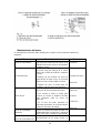
INDEX / SUMARIO / SUMÁRIO
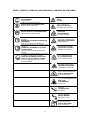
SAFETY SYMBOLS / SIMBOLOS DE SEGURANÇA / SIMBOLOS DE SEGURIDAD
.................................................................................................................................. 5
1. SPECIFICATIONS / ESPECIFICAÇÕES TÉCNICAS / ESPECIFICACIONES ....... 6
3. ENGINE ASSEMBLY AND ENGINE MACHINE COUPLING ................................. 7
4. engine operation .................................................................................................... 8
5. ENGINE ADJUSTMENT AND MAINTENANCE ................................................... 11
6. montagem do motor e acoplamento da máquina acionada com o motor ............. 17
7. OPERAÇÃO DO MOTOR .................................................................................... 17
8. Partida do motor .................................................................................................. 19
9. Parada do motor .................................................................................................. 20
10. AJUSTE E MANUTENÇÃO DO MOTOR ......................................................... 21
11. INTRODUCCIONes de seguridad .................................................................... 26
12. MONTAJE DEL MOTOR Y ACOPLAMIENTO DE LA MÁQUINA ACCIONADA
CON EL MOTOR ........................................................................................................ 26
13. OPERACIÓN DEL MOTOR .............................................................................. 27
14. AJUSTE Y MANTENIMIENTO DEL MOTOR ................................................... 31
15. WARRANTY TERM.......................................................................................... 36
16. TERMO DE GARANTIA ................................................................................... 37
17. TERMINO DE GARANTIA................................................................................ 38

4
PREFACE
Thank you for purchasing TOYAMA product.
This manual covers the operation and maintenance of a Toyama product. The information and
specifications included in this publication were in effect at the time of approval for printing. No part
of this publication may be reproduced without written permission. This manual should be
considered a permanent part of this product and should remain with it. The illustration may vary
according to the type.
Keep this owner’s manual handy, so you can refer to it at any time. This owner’s manual is
considered a permanent part of the product and should remain with the product if resold.
If a problem should arise, or if you have any questions about the product, consult you authorized
dealer.
PROLOGO
Gracias por comprar este Producto TOYAMA.
Este manual cubre la operación y el mantenimiento de este producto.La información y las
especificaciones incluidas en esta publicación son efectivas para la fecha de aprobación de
impresión.
Ninguna parte de esta publicación puede ser reproducida sin autorización.Este manual debe ser
considerado parte permanente del producto y debe mantenerse con el producto en caso de ser
revendido.Algunos detalles podrán cambiar dependiendo del modelo.
Conserve este manual a la mano para que usted se pueda referir a él em cualquier momento.
En caso de presentarse algún problema, o si usted tienen alguna pregunta sobre el producto,
contacte a su distribuidor TOYAMA.
PREFACIO
Obrigado por adquirir um Produto TOYAMA.
Este manual contém informações para operação e manutenção do seu produto. As informações
e especificações incluídas nesta publicação estavam em vigor no momento da aprovação para
impressão. Nenhuma parte desta publicação pode ser reproduzida sem permissão por escrito. A
ilustração pode variar de acordo com cada modelo de equipamento.
Mantenha este manual do proprietário sempre disponível, para que consiga consultá-lo a
qualquer momento. Este manual é considerado uma parte permanente do seu produto e deve
acompanhar o equipamento ao ser revendido.
Ao surgir um problema, ou se você tem dúvidas sobre o seu produto, consulte o seu revendedor
autorizado TOYAMA.

5
SAFETY SYMBOLS / SIMBOLOS DE SEGURANÇA / SIMBOLOS DE SEGURIDAD
LEIA O MANUAL
LEA EL MANUAL
READ MANUAL
AVISO
AVISO
WARNING
USAR PROTEÇÃO DE OUVIDO
UTILICE PROTECCIÓN AURICULAR
WEAR EAR PROTECTORS
RISCO ELÉTRICO
RIESGO ELÉCTRICO
WARNING ELECTRICITY
USAR PROTEÇÃO RESPIRATÓRIA
UTILICE PROTECCIÓN RESPIRATORIA
RESPIRATORY PROTECTION
RISCO DE TOMBAMENTO
RIESGO DE
DEZLIZAMIENTO
TIPOVER HAZARD
LUVAS DE SEGURANÇA DEVEM SER
USADAS
DEBEN SER UTILIZADOS GUANTES DE
SEGURIDAD
SAFETY GLOVES MYST BE WORN
RISCO DE QUEIMADURA
RIESGO DE QUEMADURA
BURN HAZARD
CALÇADOS DE PROTEÇÃO DEVEM SER
USADOS
DEBEN SER UTILIZADOS CALÇADOS
PROTECTORES
PROTECTIVE FOOTWEAR MUST BE
WORN
SUPERFICIE QUENTE
SUPERFICIE CALIENTE
HEAT/HOT SURFACE
PROTEÇÃO PARA OS OLHOS, OUVIDOS
E CABEÇA DEVEM SER USADOS
DEBE SER UTILIZADA PROTECCIÓN
PARA LOS OJOS, OIDOS Y CABEZA
EAR, EYE AND HEAD PROTECTION
MUST BE WORN
ALTA TEMPERATURA
ALTA TEMPERATURA
HIGH TEMPERATURE
MATERIAL INFLAMÁVEL
MATERIAL INFLAMABLE
FLAMMABLE MATERIAL
RISCO DE ESCORREGAR
RIESGO DE DESLIZAR
RISK OF SLIPPING
AR COM CONTAMINANTES
AIRE COM
CONTAMINATES
TOXIC AIR
REBOTE
CONTRAGOLPE
KICKBACK
PARTES MÓVEIS
PARTES MOBILES
ROTATING PARTS
RISCO DE LESÃO
RIESGO DE LESION
RISK OF INJURY

6
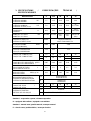
1. SPECIFICATIONS / ESPECIFICAÇÕES TÉCNICAS /
ESPECIFICACIONES
DESCRIPTION / DESCRIÇÃO /
DESCRIPCION
TDWE
8
TDWE
12.5
TDWE
18
TDWE
22
TDWE
30
MAXIMUM POWER
POTÊNCIA MÁXIMA HP
POTENCIA MAXIMA
7.7
12.5
16.5
24.0
30.0
CONTINUOUS POWER
POTÊNCIA NOMINAL HP
POTENCIA ACTIVA (12 H)
7.0
11.5
15.0
20.0
25
27.5 (HD)
CYLINDER
CILINDRADA cc
CILINDRO
402
638
903
1194
1473
1592 (HD)
BORE X STROKE
DIÂMETRO X CURSO mm
DIAMETRO X CURSO
80 x 80
90 x 95
110 x
115
115 x
115
120 x 125
120 X 130
(HD)
INJECTION SYSTEM
SISTEMA DE INJEÇÃO
SISTEMA DE INYECCION
SWIRL
DIRECT INJECTION
INJEÇÃO DIRETA
INYECCION DIRECTA
MAXIMUM SPEED
ROTAÇÃO MÁXIMA RPM
ROTACION MAXIMA
2600
2400
2200
COMPRESSION RATE
TAXA DE COMPRESSÃO
TASA DE COMPRESION
22:1
18:1
17:1
FUEL TANK
TANQUE DE COMBUSTIVEL
TANQUE DE COMBUSTIBLE
STD
7.5
11
18
22
22
R
8
10
15
20
20
RE
17
17
FUEL CONSUMPTION
CONSUMO DE COMBUSTÍVEL g/HP.h
CONSUMO DE COMBUSTIBLE
<287
<249
<257
<248
<247
OIL CAPACITY
CAPACIDADE DE ÓLEO L
CAPACIDAD DE ACEITE
2.0
2.3
3
3.2
3.2
NOISE LEVEL
NÍVEL DE RUÍDO dB(A) @ 7m
NIVEL DE RUIDO
105
107
108
109
110
REFRIGERATION SYSTEM /
SISTEMA DE REFRIGERAÇÃO
SISTEMA DE REFRIGERACION
STD
EVAPORATIVE
EVAPORATIVO
R
RADIATOR
RADIADOR
WATER TANK
TANQUE DE ÁGUA l
TANQUE DE AGUA
STD
7
11
20
20
22
R
3
3.5
4.5
5
5.5
STARTER SYSTEM
SISTEMA DE PARTIDA
SISTEMA DE ARRANQUE
STD
MANUAL
E
ELECTRIC / ELETRICA / ELECTRICA
Standard – evaporative system / sistema evaporativo
R – equipped with radiator / equipado com radiador
Standard – manual start / partida manual / arranque manual
E – electric start / partida elétrica / arranque electrico

7
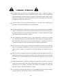
2. SAFETY INSTRUCTION
✓ It is forbidden to touch parts at high temperature such as water radiator and muffler
(exhaust), and moving parts such as the steering wheel and starter shaft to prevent burns
and injuries. Keep the fuel tank away from fire and never direct the exhaust from
flammable products such as straw, mounds of grass and cotton to avoid any scratches.
✓ Children, the elderly who move slowly and people with abnormal behavior should not be
allowed in the workplace.
✓ When coupled with the driven engines, the motor must develop its nominal power at rated
speed as specified at the manual, avoid operating the motor with overload, over speed
or with low load and at low speed for a time of 5 minutes.
✓ Use fuel and lubricating oil to the specified degree, and before use, must be thoroughly
filtered. Any utensils used should be kept clean. The used lubricating oil should be
changed periodically. The fuel filter element and the crankcase filter screen should be
cleaned periodically.
✓ Fill the oil filter with oil to the level line. Cleaning, maintenance and oil change should be
carried out regularly. When the engine is used in very windy and dusty conditions,
cleaning, maintenance and oil change should be performed every day.
✓ Clean fresh water is used for cooling water. The engine must operate under boiling
conditions of the cooling water in the radiator. The amount of water must be maintained
so that the red ball of the float should not be below the mouth of the radiator hopper.
✓ Regularly check the mounting connection and tighten the bolts of the engine parts. If you
find any loose parts, tighten immediately. (Engine sockets are provided for use during
transportation, cannot be installed in the motor for normal operation, which could damage
the motor.)
✓ The gearbox mounted fuel controller has been adjusted and sealed prior to dispatching
the engine. Do not remove or adjust randomly.
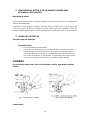
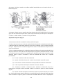
3. ENGINE ASSEMBLY AND ENGINE MACHINE COUPLING
Engine assembly
The motor must be screwed into a rigid base with the same mounting dimensions of diesel
engines of this type.
The axial dimensions of the pulley of the driven machine must coincide with those of the motor to
prevent twisting of the belts. The motor and the driven machine must be tightly coupled. Measures
must be taken to protect the steering wheel and belt pulley to avoid risk of accident.

8
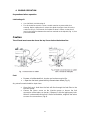
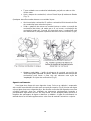
4. ENGINE OPERATION
Preparations before operation
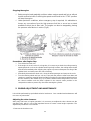
Lubricating oil:
• Use SAE20W / 40 lubricating oil
• The oil should be stored in a clean, sealed container to prevent dirt from
entering. Before adding the oil, remove the dipstick and put clean oil into the
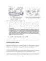
crankcase (Fig.1). The amount of oil added is about 3.5 liters so that the oil
level in the sump lies between the two lines marked on the dipstick (Fig. 2). See
purchased model
Caution
The oil level must never be above the top line or below the bottom line.
Fuel:
• Beware of adulterated fuel, impairs and reduces engine life.
• • Open the fuel tank, place the fully filtered clean diesel (Fig. 3).
Any utensils used should be kept clean.
• Open fuel cock. And then the fuel will flow through the fuel filter to the
injection pump.
• Loosen the return screw on the injection pump or loosen the fuel
connection of the tubes, so that air, if present, in the fuel piping may leak.
When it is observed that the fuel is free of air bubbles, retighten the return
screw or the connections (Fig.4).

9
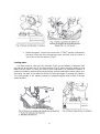
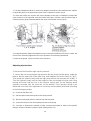
• Adjust the speed - control lever knob to the "START" position indicated on
the panel. Move the fuel priming lever back and forth until you notice a
"jolt" action of the fuel injector (Fig.5).
Cooling water:
Use fresh water to clean just like rainwater. Place on the radiator / evaporator until
the red ball of the float rises to its upper position (Fig.6). Never use dirty water or hard
water like well water. In case you need to use hard water in a particular condition, a
treatment should be performed by simply boiling and precipitating the water before use.
Otherwise, the salts in the water can block the water passages or damage the radiator.
The cooling water in the radiator should be changed regularly and be free of foreign
matter and dirt..

10
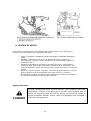
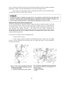
Starting the engine
A careful check should be performed after the preparation mentioned above. Then start the
engine according to the following procedure:
✓ Adjust speed → Control knob in the "START" position indicated on the panel.
✓ Insert the crank into the bore of the starting shaft. Push the pressure relief lever and
start the engine until you see a normal fuel injection sound (Fig. 7).
✓ Increase the speed of the engine drive to make the steering wheel gain sufficient
inertia, then suddenly release the pressure relief lever, but continue to drive the
engine with effort. Then the engine should start running by itself.
✓ After starting the engine, the starting crank, due to the action of the spiral claws on
the coupling side, should release by itself, and therefore the operator must continue
to hold the crank firmly and remove gently from the shaft bore. departure to avoid
any accident.
Engine operation
CAUTION
✓ After starting the engine, check the red buoy on the oil gauge and see if it has
gone up. In case of not rising or falling suddenly, stop the engine and fill with
enough oil or solve the problem.
✓ Allow engine to run at low speed for 3-5 minutes after starting. When the
cooling water temperature is relatively high, the engine speed and load
gradually increase. Never operate the engine at full speed and full load
immediately after starting.
✓ The water in the radiator / evaporator will boil during the operation of the
engine. An enough fresh water should be fed as soon as the red ball of the
float descends to the mouth of the radiator / evaporator funnel.
✓ The engine should not run on black smoke coming out of the exhaust. During
engine operation, the operator should pay close attention to the color of the
exhaust fumes. If black smoke is found in the exhaust, if all else is normal,
the engine load should be reduced or the problem solved.
✓ Never operate the motor with overload and never remove the fuel seal to
obtain excessive engine output.
✓ If any abnormal noise is observed during engine operation, stop immediately
to check.
✓ An engine must not be operated at full load during its first 50 hours of
operation. After a period of 50 hours, all bolts and nuts must be checked and
retightened.
During engine operation, take precautions against pulley, burn and
fire accidents. We expect the operator to pay attention to the
safety marks near the fuel tank nozzle, radiator water tank cover,
steering wheel, gearbox starting shaft to muffler (exhaust).

11
Stopping the engine
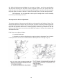
✓ Reduce engine load gradually and then reduce engine speed and let run without
load for several minutes. Switching the speed control lever to the "STOP" position
will stop the engine.
✓ Under particular conditions, when emergency stop is required, it is advisable to
loosen any connections from the high pressure fuel line or use a tow or towel
available to block the air filter inlet. The engine can also be stopped by placing
the pressure relief device in action (Fig.8).
Precautions after Engine Stop
✓ Turn off the fuel tank cock.
✓ If the engine is out of service for a long time, it is necessary to drain the cooling water by
opening the drain cock on the cylinder head. Especially in winter, the cooling water should
be drained immediately after stopping the engine to prevent subsequent cracking of the
cylinder block and other parts also due to freezing.
✓ Periodically dismantle the drain cock, clean the water passages and remove the scale.
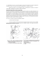
✓ Turn the steering wheel until you can not. Then push the pressure relief lever down and
continue to rotate the steering wheel until the line marked on the steering wheel matches
the line marked on the radiator (Fig. 9), so that the intake and discharge valves are set in
the closed condition and the piston adjusted in the neutral center position in the
compression stroke to prevent any dust from entering the cylinder.
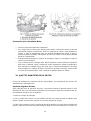
5. ENGINE ADJUSTMENT AND MAINTENANCE
It should be performed by specialized technical assistance. Your unauthorized maintenance will
not cover any warranties.
Adjusting the valve clearance
After every 500 hours of engine operation, it is necessary to readjust the valve clearance to the
specified value, which is one of the important factors to ensure normal engine operation. The
adjustment procedures are as follows:
1. Remove the headset cover.

12
2. Turn the handwheel until the T mark on its periphery matches the line marked on the radiator
to adjust the piston in the upper dead center in the compression stroke. (Fig.9).
3. Loosen the locking nut and turn the rocker adjusting screw with a screwdriver to adjust the
valve clearance to the specified value (the intake valve gap is 0.35mm, and the exhaust gap is
0.45mm) using a gauge inserted between the valve stem and the rocker (Fig.10).
4. During adjustment, tighten the adjusting screw so that the tensioning rod is free to rotate, but
not too loose. After that, tighten the lock nut to prevent it from loosening afterwards.
5. Remove the gauge, and re-check the valve clearance.
Adjusting injection time
1. Disconnect fuel line from high injector pressure.
2. Loosen the nut connecting the high pressure fuel line to the injection pump, rotate the
tube so that the open side of the tube is up, and retighten the nut as shown in Fig.11.
Then prime the injection pump until the high pressure fuel line becomes full of fuel. 3.
Turn the flywheel slowly until the fuel begins to flow out through the pipe stub. Stop
turning and check that the line of the injection timing mark on the steering wheel
periphery coincides with the mark line on the radiator. If the injection timing is too
advanced or too late, then adjustment is necessary and should be performed according
to the following procedure.
(1) – Close the fuel filter cock.
(2) - Set the speed control lever knob to the center position.
(3) - Disconnect the high pressure fuel line from the fuel pump.
(4) - Loosen the fixing screws of the pump and remove the pump.
(5) - Increase or decrease the number of joints. Increase the number of shims if the injection
timing is advanced. Reduce number of joints if delayed (Fig. 12)

13
(6) - Refit the injection pump and tighten the set screws. In doing so, special care must be taken
with the piston adjusting arm ball which must be engaged in the slot on the speed control fork
inside the gear case. This should be checked again through the inspection hole after mounting
the pump again to avoid the "deviation" of the motor resulting from a possible wrong assembly.
After adjustment, it is recommended to check again according to item 3 above. Resetting
is necessary if something is incorrect.
Decompression Device Adjustment
The proper operation of the pressure relief device can be tested by hand feeling as follows: Turn
the pressure relief lever clockwise with your left hand, and at the same time, start the engine with
your right hand using the starting crank. If your left hand becomes heavy while your right hand is
light, then the pressure relief device is working properly. However, pay attention so that the
pressure relief shaft does not touch the rocker while the engine is running, after releasing the
decompression lever.
If this is the case, adjust as follows:
1. Loose the locking nut..
2. Rotate the eccentric bushing through an angle to make the adjustment. Turn clockwise
if decompression is too low, turn counterclockwise if decompression is too high. (Fig. 13).

14
Engine maintenance
Maintenance of the engine must be carried out according to the following items and
requirements:
Item
Maintenance
Period
Cooling water
As soon as the red ball of the float on the
radiator drops down near the mouth of the
funnel, complete the water
As required
Lubricant
- As soon as the engine crankcase oil level
falls below the lower mark on the dipstick,
complete the oil.
- After the first 50 hours of operation of a
new engine, it is necessary to clean the
crankcase and change the oil.
- After this, the oil must be changed every
100 hours of operation.
Daily
First 50 hours
100 hours
Air filter
- Normally, the filter should be cleaned
every 100 hours of engine operation.
- But when the motor is used to drive a
tractor, cleaning the filter must be
performed every 50 hours of operation.
- In the case of a motor operating in a dusty
atmosphere, it is necessary to clean the
filter every working shift.
100 hours
50 hours
Each use
Fuel filter elemento
Clean the filter paper element with clean
fuel or kerosene and blow from the inside
out, replace if damaged.
100 hours
Oil filter
After the first 50 hours of operation of a new
engine, it is necessary to remove the filter
and clean it.
After this, the filter should be cleaned every
100 hours of operation.
First 50 hours
100 hours

15
Porca do cabeçote
Reapertar a porca do cabeçote com um
torque de 274,4 ~ 313,6 N.m após as
primeiras 30 horas de operação de um
motor novo.
First 30 hours
Fuel tank and fuel filter
- Remover o filtro da entrada do tanque de
combustível e limpar com combustível
limpo.
- Limpar o interior do tanque de combustível
com combustível limpo.
50 hours
500 hours
Valve polishing
Lubricate the valve seat with a little
polishing paste and polish carefully.
(Caution: do not allow the polishing paste to
enter the valve guides).
After polishing, flush valves and valve seats
with clean fuel and dry. Check the valve
tightening by spilling a small amount of fuel
into the suction and exhaust, observing
whether it leaks around the valve seats.
500 hours
Valve clearence
Adjust according to recommended
procedure.
100 hours
Cylinder head, cylinder
liner and piston
connecting rod assembly
Remove coal deposits, if any, and clean
with clean fuel. It may not be necessary to
disassemble for cleaning if the engine.
1000 hours
Oil ducts on the
crankshaft shaft
Clean the center hole of the axle pin and the
oil passages on the crankshaft shaft with
clean fuel.
200 hours
Cooling water passages
Fill the water passages with a 25%
concentration of hydrochloric acid (HCl),
hold for about 10 minutes and then blow-
rinse with fresh water. Repeat if not
completely clean.
Note: The radiator must be removed from
the engine before cleaning.
500 hours
Fuel Injector
Check the fuel injection pressure and spray
gun. Usually, the spray has a pattern of 4
concentrated jets and no fuel drip or spray
jet. If necessary, clean the coupling of the
nozzle and remove the coal deposits inside
the injection holes with a 0.3 mm needle. In
case of dripping of fuel and no clear
"trepidation" during spraying, it is necessary
to polish the coupling surfaces of the
coupling of the nozzle with a little polishing
paste. Then wash and reassemble. Reset
the fuel injection pressure again.
As required
.

16
CUIDADO / ATENÇÃO
✓ É proibido tocar nas peças em alta temperatura tais como o radiador de água e
silenciador (escapamento), e peças móveis tais como o volante e eixo de partida para
evitar queimaduras e lesões. Manter o tanque de combustível longe do fogo e nunca
direcionar o escapamento contra produtos inflamáveis tais como palha, montes de capim
e algodão para evitar quaisquer riscos.
✓ Crianças, idosos que se movimentam lentamente e pessoas com comportamentos
anormais não devem ser permitidos no local de trabalho.
✓ Quando acoplado com as máquinas acionadas, o motor deve desenvolver sua potência
nominal na velocidade nominal conforme especificado no final do manual, evitar operar
o motor com sobrecarga, com excesso de velocidade ou com carga reduzida e em baixa
velocidade durante um tempo de 5 minutos.
✓ Usar combustível e óleo lubrificante com o grau especificado, e antes de usar, devem
ser completamente filtrados. Quaisquer utensílios usados devem ser mantidos limpos. O
óleo lubrificante usado deve ser trocado periodicamente. O elemento do filtro de
combustível e a peneira do filtro do cárter devem ser limpos periodicamente.
✓ Encher o filtro de ar com óleo até a linha de nível. A limpeza, manutenção e troca de óleo
devem ser realizadas regularmente. Quando o motor é usado em condições de muito
vento e poeira, a limpeza, manutenção e troca de óleo devem ser realizadas todos os
dias.
✓ Água doce limpa é usada para água de resfriamento. O motor deve operar em condições
de ebulição da água de resfriamento no radiador. A quantidade de água deve ser mantida
de modo que a esfera vermelha da boia não deve ficar abaixo da boca do funil do
radiador.
✓ Verificar regularmente a conexão de montagem e o aperto dos parafusos das peças do
motor. Se encontrar qualquer peça solta, apertar imediatamente. (As bases do motor são
fornecidas para uso durante o transporte, não podem ser instaladas no motor para
operação normal, o que poderia danificar o motor).
✓ O controlador de combustível montado na caixa de engrenagens foi ajustado e vedado
antes do despacho do motor. Não remover ou ajustar aleatoriamente.

17
6. MONTAGEM DO MOTOR E ACOPLAMENTO DA MÁQUINA
ACIONADA COM O MOTOR
Montagem do motor
O motor deve ser parafusado em uma base rígida com as mesmas dimensões de montagem dos
motores Diesel deste tipo.
As dimensões axiais da polia da máquina acionada devem coincidir com as do motor para evitar
torção das correias. O motor e a máquina acionada devem estar bem acoplados. Devem ser
tomadas medidas para proteção do volante e da polia das correias para evitar riscos de acidente.
7. OPERAÇÃO DO MOTOR
Preparos antes da operação
Òleo lubrificante:
• Usar óleo lubrificante SAE20W/40
• O óleo deve ser armazenado em um recipiente limpo e vedado para evitar a
entrada de sujeira. Antes de adicionar o óleo, retirar a vareta de medição e
colocar óleo limpo no cárter (Fig.1). A quantidade de óleo adicionada é cerca
de 3,5 litros de modo que o nível de óleo no cárter fique entre as duas linhas
marcadas na vareta de medição (Fig.2). Consulte modelo adquirido
CUIDADO
O nível de óleo nunca deve ficar acima da linha superior, nem abaixo da linha
inferior.
Combustível:

18
• Tomar cuidado com combustível adulterado, prejudica e reduz a vida
útil do motor.
• Abrir o tanque de combustível, colocar Diesel limpo já totalmente filtrado
(Fig. 3).
Quaisquer utensílios usados devem ser mantidos limpos.
• Abrir torneira de combustível. E então o combustível fluirá através do filtro
de combustível para a bomba injetora.
• Soltar o parafuso de retorno na bomba injetora ou soltar a conexão de
combustível dos tubos, de modo que o ar, se houver, na tubulação do
combustível pode sair. Quando for observado que o combustível está
sem bolhas de ar, reapertar o parafuso de retorno ou as conexões (Fig.4).
• Ajustar a velocidade – botão da alavanca de controle na posição de
“PARTIDA”(Start) indicada no painel. Mover a alavanca de escorva do
combustível para frente e para trás até observar uma ação de
“trepidação” do injetor de combustível (Fig.5).
Água de resfriamento:
Usar água doce limpar tal como água de chuva. Colocar no radiador / evaporador
até a esfera vermelha da boia subir para sua posição superior (Fig.6). Nunca usar água
suja ou água dura como a água de poço. No caso de necessitar usar água dura em uma
condição particular, deve ser realizado um tratamento simplesmente fervendo e
precipitando a água antes de usar. De outra forma, os sais da água podem provocar o
bloqueio das passagens de água ou danificar o radiador. A água de resfriamento no
radiador deve ser trocada regularmente e estar livre de materiais estranhos e sujeira.

19
8. PARTIDA DO MOTOR
Uma verificação cuidadosa deve ser realizada após o preparo citado acima. Depois dar a
partida no motor de acordo com o seguinte procedimento:
✓ Ajustar a velocidade → Botão de controle na posição de “PARTIDA” indicada no
painel.
✓ Introduzir a manivela no furo do eixo de partida. Empurrar a alavanca de
descompressão e acionar o motor, até observar um som normal de injeção de
combustível (Fig. 7).
✓ Aumentar a velocidade do acionamento do motor para fazer o volante ganhar
inércia suficiente, depois soltar subitamente a alavanca de descompressão, mas
continuar acionando o motor com esforço. Então o motor deve começar a funcionar
sozinho.
✓ Depois que o motor começar a funcionar, a manivela de partida, devido a ação das
garras espirais no lado de acoplamento, deve soltar sozinha, e, portanto, o
operador deve continuar segurando a mesma firmemente e retirar suavemente do
furo do eixo de partida para evitar qualquer acidente.
Operação do motor
CUIDADO
Durante a operação do motor, tomar precauções contra acidentes com polias,
queimadura e incêndio. Esperamos que o operador preste atenção para as
marcas de segurança perto do bocal do tanque de combustível, tampa do
tanque de água do radiador, volante, caixa de engrenagens eixo de partida a
silenciador (escapamento).

20
✓ Após a partida do motor, verificar a boia vermelha no indicador de óleo e ver
se subiu. No caso de não subir ou cair subitamente, parar o motor e encher
com uma quantidade suficiente de óleo ou resolver o problema.
✓ Deixar o motor operar sem carga em baixa velocidade durante 3-5 minutos
após sua partida. Quando a temperatura da água de resfriamento ficar
relativamente alta, aumenta gradualmente a velocidade e a carga do motor.
Nunca operar o motor em alta velocidade e com carga total imediatamente
após a partida.
✓ A água no radiador / evaporador fica fervendo durante a operação do motor.
Uma quantidade suficiente de água doce deve ser alimentada logo que a
esfera vermelha da boia descer para a boca do funil do radiador / evaporador.
✓ O motor não deve funcionar com fumaça negra saindo do escapamento.
Durante o funcionamento do motor, o operador deve prestar bastante
atenção com a cor da fumaça do escapamento. No caso de encontrar fumaça
negra no escapamento, se todo o resto estiver normal, a carga do motor deve
ser reduzida ou o problema deve ser resolvido.
✓ Nunca operar o motor com sobrecarga e nunca remover o lacre de
combustível para obter rendimento excessivo do motor.
✓ Se observar algum ruído anormal durante a operação do motor, parar
imediatamente para verificar.
✓ Um motor não deve ser operar com carga total durante suas primeiras
50horas de operação. Após um período de 50horas, é necessário verificar e
reapertar todos os parafusos e porcas.
9. PARADA DO MOTOR
✓ Reduzir a carga do motor gradualmente e depois reduzir a velocidade do
motor e deixar funcionar sem carga durante diversos minutos. Mudar o botão da
alavanca de controle da velocidade para a posição “PARADA”(Stop), então o
motor parará de funcionar.
✓ Em condições particulares, quando a parada de emergência é
necessária, é recomendável soltar quaisquer conexões do tubo de combustível
de alta pressão ou usar uma estopa ou toalha disponível para boquear a entrada
do filtro de ar. O motor também pode ser parado colocando o dispositivo de
descompressão em ação (Fig.8).
A página está carregando...
A página está carregando...
A página está carregando...
A página está carregando...
A página está carregando...
A página está carregando...
A página está carregando...
A página está carregando...
A página está carregando...
A página está carregando...
A página está carregando...
A página está carregando...
A página está carregando...
A página está carregando...
A página está carregando...
A página está carregando...
A página está carregando...
A página está carregando...
A página está carregando...
A página está carregando...
-
 1
1
-
 2
2
-
 3
3
-
 4
4
-
 5
5
-
 6
6
-
 7
7
-
 8
8
-
 9
9
-
 10
10
-
 11
11
-
 12
12
-
 13
13
-
 14
14
-
 15
15
-
 16
16
-
 17
17
-
 18
18
-
 19
19
-
 20
20
-
 21
21
-
 22
22
-
 23
23
-
 24
24
-
 25
25
-
 26
26
-
 27
27
-
 28
28
-
 29
29
-
 30
30
-
 31
31
-
 32
32
-
 33
33
-
 34
34
-
 35
35
-
 36
36
-
 37
37
-
 38
38
-
 39
39
-
 40
40


em outras línguas
- español: TOYAMA TDWE22-XP El manual del propietario
- English: TOYAMA TDWE22-XP Owner's manual
Artigos relacionados
-
TOYAMA TDWP50CS-GII Manual do proprietário
-
-
-
-
-
-
-
-
-