
Refer All Communications to the Nearest
Ingersoll–Rand Office or Distributor.
Ingersoll–Rand Company 1999
Printed in U.S.A.
03528676
Form P6403
Edition 8
August, 1999
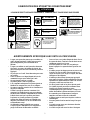
OPERATION AND MAINTENANCE MANUAL FOR
MODELS 341 AND 441 TAMPERS
Models 341 and 441 Tampers are designed for compacting sand in floor–level molds and patterns in
foundry applications and tamping backfill in construction applications.
Ingersoll–Rand is not responsible for customer modification of tools for applications on which
Ingersoll–Rand was not consulted.
IMPORTANT SAFETY INFORMATION ENCLOSED.
READ THIS MANUAL BEFORE OPERATING TOOL.
IT IS THE RESPONSIBILITY OF THE EMPLOYER TO PLACE THE INFORMATION
IN THIS MANUAL INTO THE HANDS OF THE OPERATOR.
FAILURE TO OBSERVE THE FOLLOWING WARNINGS COULD RESULT IN INJURY.
PLACING TOOL IN SERVICE
• Always operate, inspect and maintain this tool in
accordance with American National Standards
Institute Safety Code for Porable Air Tools (ANSI
B186.1).
• For safety, top performance, and maximum
durability of parts, operate this tool at 90 psig (6.2
bar/620 kPa) maximum air pressure at the inlet
with 1/2” (13 mm) inside diameter air supply hose.
• Always turn off the air supply and disconnect the
air supply hose before installing, removing or
adjusting any accessory on this tool, or before
performing any maintenance on this tool.
• Do not use damaged, frayed or deteriorated air
hoses and fittings.
• Be sure all hoses and fittings are the correct size
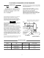
and are tightly secured. See Dwg. TPD905–1 for a
typical piping arrangement.
• Always use clean, dry air at 90 psig maximum air
pressure. Dust, corrosive fumes and/or excessive
moisture can ruin the motor of an air tool.
• Do not lubricate tools with flammable or volatile
liquids such as kerosene, diesel or jet fuel.
• Do not remove any labels. Replace any damaged
label.
USING THE TOOL
• Always wear eye protection when operating or
performing maintenance on this tool.
• Always wear hearing protection when operating
this tool.
• Keep hands, loose clothing and long hair away from
impacting end of tool.
• Note the position of the reversing lever before
operating the tool so as to be aware of the direction
of rotation when operating the throttle.
• Anticipate and be alert for sudden changes in motion
during start up and operation of any power tool.
• Keep body stance balanced and firm. Do not
overreach when operating this tool. High reaction
torques can occur at or below the recommended air
pressure.
• Tool accessory may continue to impact briefly after
throttle is released.
• Air powered tools can vibrate in use. Vibration,
repetitive motions or uncomfortable positions may
be harmful to your hands and arms. Stop using any
tool if discomfort, tingling feeling or pain occurs.
Seek medical advice before resuming use.
• Use accessories recommended by Ingersoll–Rand.
• Never operate a Percussion Tool unless an accessory
is properly installed and the tool is held firmly
against the work.
• Always use a retainer, when furnished, in addition
to proper barriers to protect persons in
surrounding or lower areas from possible ejected
accessories.
• This tool is not designed for working in explosive
atmospheres.
• This tool is not insulated against electric shock.
The use of other than genuine Ingersoll–Rand replacement parts may result in safety hazards, decreased tool
performance, and increased maintenance, and may invalidate all warranties.
Repairs should be made only by authorized trained personnel. Consult your nearest Ingersoll–Rand Authorized
Servicenter.
F
E
P

2
WARNING LABEL IDENTIFICATION
FAILURE TO OBSERVE THE FOLLOWING WARNINGS COULD RESULT IN INJURY.
Always wear eye protection
when operating or perform-
ing maintenance on this
tool.
WARNING
WARNING
Always wear hearing
protection when operating
this tool.
Always turn off the air sup-
ply and disconnect the air
supply hose before install-
ing, removing or adjusting
any accessory on this tool,
or before performing any
maintenance on this tool.
WARNING
Air powered tools can vibrate
in use. Vibration, repetitive
motions or uncomfortable po-
sitions may be harmful to your
hands and arms. Stop using
any tool if discomfort, tingling
feeling or pain occurs. Seek
medical advice before resum-
ing use.
WARNING
Do not carry the tool by
the hose.
WARNING
WARNING
Do not use damaged, frayed
or deteriorated air hoses
and fittings.
WARNING
Keep body stance balanced
and firm. Do not overreach
when operating this tool.
WARNING
Operate at 90 psig (6.2 bar/
620 kPa) Maximum air pressure.
90 psig
(6.2bar/620kPa)
PERCUSSIVE TOOL WARNINGS
• When wearing gloves and operating models with
inside trigger, always be sure that the gloves will not
prevent the trigger from being released.
• Wear safety shoes, hard hat, safety goggles, gloves,
dustmask and any other appropriate protective
clothing while operating the tool.
• Do not indulge in horseplay. Distraction can cause
accidents.
• Keep hands and fingers away from the throttle
lever until it is time to operate the tool.
• Never rest the tool or chisel on your foot.
• Never point the tool at anyone.
• Compressed air is dangerous. Never point an air
hose at yourself or co–workers.
• Never blow clothes free of dust with compressed air.
• Be sure all hose connections are tight. A loose hose
not only leaks but can come completely off the tool
and while whipping under pressure, can injure the
operator and others in the area. Attach safety
cables to all hoses to prevent injury in case a hose is
accidentally broken.
• Never disconnect a pressurized air hose. Always
turn off the air supply and bleed the tool before
disconnecting a hose.
• The operator must keep limbs and body clear of the
chisel. If a chisel breaks, the tool with the broken
chisel projecting from the tool will suddenly surge
forward.
• Do not ride the tool with one leg over the handle.
Injury can result if the chisel breaks while riding
the tool.
• Know what is underneath the material being
worked. Be alert for hidden water, gas, sewer,
telephone or electric lines.
• Use only proper cleaning solvents to clean parts.
Use only cleaning solvents which meet current
safety and health standards. Use cleaning solvents
in a well ventilated area.
• Do not flush the tool or clean any parts with diesel
fuel. Diesel fuel residue will ignite in the tool when
the tool is operated, causing damage to internal
parts. When using models with outside triggers or
throttle levers, take care when setting the tool down
to prevent accidental operation.
• Do not operate the tool with broken or damaged
parts.
• Never start the tool when it is lying on the ground.
• This tool is not designed for working in explosive
atmospheres.
• This tool is not insulated against electric shock.

3
PLACING TOOL IN SERVICE
LUBRICATION
Ingersoll–Rand No. 10 Ingersoll–Rand No. 28
Always use an air line lubricator. We recommend the
following Filter–Lubricator–Regulator Unit:
For intermittent use:
For USA – No. 6LUB12
These tools are equipped with a measured operator
controlled lubrication system. Insufficient lubrication will
cause the tool to run noticeably slower and excessive
lubrication will be blown out the exhaust and wasted.
Do not attempt to lubricate the tool with the Throttle
Lever depressed and the tool working.
After one hour of operation, or as experience on the job
indicates, release the Throttle Lever to stop the tool; push
the Lubricator Valve inward and hold it in for about ten
seconds. Release the Valve and depress the Throttle Lever
to resume work. Rapidly pushing the Lubricator Valve in
and out will not introduce a significant amount of lubricant
to the tool. The Valve must have adequate time to refill
with a measured amount of lubricant before being actuated
again.
A small amount of smoke will be visible at the exhaust
when the tool is started and it indicates that the lubrication
has entered the system. If some smoke is not visible,
remove the Oil Chamber Plug and check the oil level in the
oil chamber.
At the beginning of each work shift, or as experience
indicates, remove the Oil Chamber Plug and fill the oil
chamber with the recommended oil.
After each eight hours of operation, replenish the supply
of grease in the grease chamber. Four to six strokes from
the No. R000A2–228 Grease Gun injected through the
Grease Fitting is sufficient.
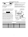
MAIN LINES 3 TIMES
AIR TOOL INLET SIZE
TO
AIR
SYSTEM
TO
AIR
TOOL
LUBRICATOR
REGULATOR
FILTER
BRANCH LINE 2 TIMES
AIR TOOL INLET SIZE
DRAIN REGULARLY
COMPRESSOR
(Dwg. TPD905–1)
HOW TO ORDER A TAMPER
FLOOR–TYPE TAMPER LEVER THROTTLE
Piston Stroke
Model
Blows/min. in mm
341 1,550 4 102
441 1,750 4 102

Adressez toutes vos communications au Bureau
Ingersoll–Rand ou distributeur le plus proche.
Ingersoll–Rand Company 1999
Imprimé aux É.U.
MANUEL D’EXPLOITATION ET D’ENTRETIEN
DAMEUSES MODÈLES 341 ET 441
NOTE
Les dameuses Modèles 341 et 441 sont destinées au compactage des moules et modèles au
sol dans les applications de fonderie et le damage des remblayages dans les applications de
construction.
Ingersoll–Rand ne peut être tenu responsable de la modification des outils par le client pour
les adapter à des applications qui n’ont pas été approuvées par Ingersoll–Rand.
ATTENTION
D’IMPORTANTES INFORMATIONS DE SECURITÉ SONT JOINTES.
LIRE CE MANUEL AVANT D’UTILISER L’OUTIL.
L’EMPLOYEUR EST TENU À COMMUNIQUER LES INFORMATIONS DE CE MANUEL
AUX EMPLOYÉS UTILISANT CET OUTIL.
LE NON RESPECT DES AVERTISSEMENTS SUIVANTS PEUT CAUSER DES BLESSURES
MISE EN SERVICE DE L’OUTIL
• Toujours exploiter, inspecter et entretenir cet outil
conformément au Code de sécurité des outils
pneumatiques portatifs de l’American National
Standards Institute (ANSI B186.1).
• Pour la sécurité, les performances optimales et la
durabilité maximale des pièces, cet outil doit être
connecté à une alimentation d’air comprimé de
6,2 bar (620 kPa) maximum à l’entrée, avec un flexible
de 13 mm de diamètre intérieur.
• Couper toujours l’alimentation d’air comprimé et
débrancher le flexible d’alimentation avant d’installer,
déposer ou ajuster tout accessoire sur cet outil, ou
d’entreprendre une opération d’entretien quelconque
sur l’outil.
• Ne pas utiliser des flexibles ou des raccords
endommagés, effilochés ou détériorés.
• S’assurer que tous les flexibles et les raccords sont
correctement dimensionnés et bien serrés. Voir Plan
TPD905–1 pour un exemple type d’agencement des
tuyauteries.
• Utiliser toujours de l’air sec et propre à une pression
maximum de 6,2 bar. La poussière, les fumées
corrosives et/ou une humidité excessive peuvent
endommager le moteur d’un outil pneumatique.
• Ne jamais lubrifier les outils avec des liquides
inflammables ou volatiles tels que le kérosène, le gasol
ou lecarburant d’aviation.
• Ne retirer aucune étiquette. Remplacer toute étiquette
endommagée.
UTILISATION DE L’OUTIL
• Porter toujours des lunettes de protection pendant
l’utilisation et l’entretien de cet outil.
• Porter toujours une protection acoustique pendant
l’utilisation de cet outil.
• Tenir les mains, les vêtements flous et les cheveux
longs, éloignés de l’extrémité percutante de l’outil.
• Noter la position du levier d’inversion avant de
mettrel’outil en marche de manière à savoir dans quel
sens il va tourner lorsque la commande est actionnée.
• Prévoir, et ne pas oublier, que tout outil motorisé est
susceptible d’à-coups brusques lors de sa mise en
marche et pendant son utilisation.
• Garder une position équilibrée et ferme. Ne passe
pencher trop en avant pendant l’utilisation de cet
outil. Des couples de réaction élevés peuvent se
produire à, ou en dessous, de la pression d’air
recommandée.
• La percussion des accessoires de l’outil peut continuer
pendant un certain temps après le relâchement de la
gâchette.
• Les outils pneumatiques peuvent vibrer pendant
l’exploitation. Les vibrations, les mouvements
répétitifs et les positions inconfortables peuvent causer
des douleurs dans les mains et les bras. N’utiliser plus
d’outils en cas d’inconfort, de picotements ou de
douleurs. Consulter un médecin avant de
recommencer à utiliser l’outil.
• Utiliser les accessoires recommandés par
Ingersoll-Rand.
• Ne jamais mettre en marche un outil à percussion à
moins qu’un accessoire soit correctement installé et
que l’outil soit maintenu fermement contre la pièce à
travailler.
• Utiliser toujours une douille de retenue, lorsque
fournie, en plus des protections habituelles pour la
sécurité du personnel travaillant dans les zones
environnantes contre l’éjection possible des
accessoires.
• Cet outil n’est pas conçu pour fonctionner dans des
atmosphères explosives.
• Cet outil n’est pas isolé contre les chocs électriques.
NOTE
L’utilisation de rechanges autres que les pièces d’origine Ingersoll–Rand peut causer des risques d’insécurité, réduire les
performances del’outil et augmenter l’entretien, et peut annuler toutes les garanties.
Les réparations ne doivent être effectuées que par des réparateurs qualifiés autorisés. Consultez votre Centre de Service
Ingersoll–Rand le plus proche.
F

5
SIGNIFICATION DES ETIQUETTES D’AVERTISSEMENT
ATTENTION
LE NON RESPECT DES AVERTISSEMENTS SUIVANTS PEUT CAUSER DES BLESSURES
Porter toujours des lunettes
de protection pendant
l’utilisation et l’entretien de
cet outil.
ATTENTION ATTENTION
Porter toujours une
protection acoustique
pendant l’utilisation de cet
outil.
Les outils pneumatiques
peuvent vibrer pendant
l’exploitation. Les vibrations,
les mouvements répétitifs et les
positions inconfortables
peuvent causer des douleurs
dans les mains et les bras.
N’utiliser plus d’outils en cas
d’inconfort, de picotements ou
de douleurs. Consulter un
médecin avant de recommencer
à utiliser l’outil.
ATTENTION
Ne pas transporter l’outil
par son flexible.
ATTENTION
ATTENTION
Garder une position équilibrée et
ferme. Ne pas se pencher trop
en avant pendant
l’utilisation de cet outil.
ATTENTION
Utiliser de l’air comprimé
à une pression maximum
de 6,2 bar (620 kPa).
90 psig
(6.2bar/620kPa)
Couper toujours l’alimentation
d’air comprimé et débrancher le
flexible d’alimentation avant
d’installer, déposer ou ajuster
tout accessoire sur cet outil, ou
d’entreprendre une opération
d’entretien quelconque sur l’ou-
til.
ATTENTION
ATTENTION
Ne pas utiliser des flexibles ou
des raccords endommageés,
effilochés ou détériorés.
AVERTISSEMENTS SPÉCIFIQUES AUX OUTILS À PERCUSSION
• Lorsque vous portez des gants et que vous utilisez un
outil à gâchette intérieure, vérifiez toujours que les
gants n’empêcheront pas le relâchement de la
gâchette.
• Lorsque vous utilisez cet outil, portez des chaussures
de sécurité, un casque, des lunettes de sécurité, des
gants, un masque et tout autre vêtement de protection
approprié.
• Ne jouez pas avec l’outil. Toute distraction peut causer
un accident.
• Tenez vos mains et vos doigts éloignés du levier de
commande lorsque vous n’utilisez pas l’outil.
• Ne posez jamais l’outil sur vos pieds.
• Ne pointez jamais l’outil vers quelqu’un.
• L’air comprimé est dangereux. Ne pointez jamais un
flexible d’air comprimé sur vous ou vos collègues.
• Ne nettoyez jamais la poussière de vos vêtements avec
un jet d’air comprimé.
• Vérifiez le serrage de toutes les connexions d’air
comprimé. Un flexible desserré peut non seulement
fuir mais aussi se détacher complètement de l’outil et
l’effet de fouet causé par la pression peut blesser
l’opérateur ou d’autres personnes à proximité.
Attacher des câbles de sécurité sur le flexible pour
empêcher toute blessure au cas où le flexible serait
accidentellement coupé.
• Ne débranchez jamais un flexible sous pression.
Coupez toujours l’alimentation d’air comprimé et
purgez l’outil avant de débrancher un flexible.
• Tenez vos bras et vos jambes éloignés du burin. En cas
de rupture du burin, l’outil et le reste du burin seront
violemment projetés vers l’avant.
• Ne montez jamais sur l’outil avec une jambe par
dessus la poignée. La rupture du burin pourrait vous
blesser.
• N’oubliez pas que des dangers peuvent se trouver sous
la surface où vous travaillez. Prenez soin de ne pas
couper des tuyaux d’eau, de gaz ou d’égout, des câbles
électriques ou de téléphone.
• N’utilisez que des solvants de nettoyage appropriés
pour nettoyer les pièces. Utilisez seulement les solvants
répondant aux réglementations de santé et de sécurité
en vigueur, et dans une zone bien aérée.
• Ne rincez jamais l’outil ou les pièces dans du gazole.
Les résidus de gazole pourraient s’enflammer dans
l’outil lors de sa mise en marche et causer
l’endommagement des pièces internes. Lorsque vous
utilisez des modèles à gâchette extérieure ou à levier
de commande, posez soigneusement l’outil pour
empêcher toute mise en marche accidentelle.
• N’utilisez jamais un outil ayant des pièces cassées ou
endommagées.
• Ne mettez jamais l’outil en marche lorsqu’il est posé
au sol.
• Cet outil n’est pas conçu pour fonctionner dans des
atmosphères explosives.
• Cet outil n’est pas isolé contre les chocs électriques.

6
MISE EN SERVICE DE L’OUTIL
LUBRIFICATION
Ingersoll–Rand No. 10 Ingersoll–Rand No. 28
Utiliser toujours un lubrificateur. Nous recommandons
l’emploi du filtre–régulateur–lubrificateur suivant :
Pour usage intermittent :
É.U. – No. 6LUB12
Ces outils sont équipés d’un système de lubrification à dosage
contrôlé par l’opérateur. Une lubrification insuffisante causera
une réduction notable de la vitesse de l’outil, tandis qu’une
lubrification excessive sera évacuée par l’échappement et
gaspillée.
NOTE
Ne jamais tenter de lubrifier l’outil lorsque le levier de
commande est appuyé et que l’outil fonctionne.
Après une heure de fonctionnement, ou en fonction de
l’application, relâcher le levier de commande pour arrêter
l’outil, appuyer sur la soupape du lubrificateur et la maintenir
enfoncée pendant dix secondes environ. Relâcher la soupape
et appuyer sur le levier de commande pour recommencer à
travailler. L’appui et le relâchement rapides de la soupape du
lubrificateur n’introduiront pas une quantité importante de
lubrifiant dans l’outil. Une période adéquate doit être allouée
pour que la soupape se remplisse d’une quantité mesurée de
lubrifiant avant d’être de nouveau actionnée.
Une petite quantité de fumée, indiquant que le lubrifiant est
entré dans le système, sera visible à l’échappement lors de la
mise en marche de l’outil. En cas d’absence de fumée, déposer
le bouchon de la chambre d’huile et vérifier le niveau d’huile
dans la chambre.
Au début de chaque poste de travail, ou en fonction de
l’application, déposer le bouchon de la chambre d’huile et
remplir cette dernière avec l’huile recommandée.
Toutes les huit heures de fonctionnement, refaire le plein de
la chambre degraisse. Quatre à six coups de pistolet de
graissage R000A2–228 dans le raccord de graissage suffisent.
TUYAUTERIE PRINCIPALE
AU MOINS 3 FOIS LA
DIMENSION DE L’ADMISSION
D’AIR DE L’OUTIL
VERS LE
RÉSEAU D’AIR
COMPRIMÉ
VERS
L’OUTIL
PNEU-
MATIQUE
LUBRIFICATEUR
RÉGULATEUR
FILTRE
LIGNE SECONDAIRE AU
MOINS 2 FOIS LA
DIMENSION DE
L’ADMISSION D’AIR
DE L’OUTIL
VIDANGER
RÉGULIÈREMENT
COMPRESSEUR
(Plan TPD905–1)
SPÉCIFICATIONS
Modèle Type Coups par minute Course du piston
in (mm)
341 Commande
à levier au sol
1.550 4 (102)
441 Commande
à levier au sol
1.750 4 (102)

Toda comunicación se deberá dirigir a la oficina o al
distribuidor Ingersoll–Rand más próximo.
Ingersoll–Rand Company 1999
Impreso en EE.UU.
MANUAL DE FUNCIONAMIENTO Y MANTENIMIENTO
APISONADORAS MODELO 341 Y 441
NOTA
Las Apisonadoras Modelo 341 y 441 están diseñadas para compactar arena en aplicaciones
de moldeos de nivel de suelo y patrones de fundiciones y apisonamiento de rellenos en
aplicaciones de construcción.
Ingersoll–Rand no aceptará responsabilidad alguna por modificación de las herramientas
efectuada por el cliente para aquellas aplicaciones que no hayan sido objeto de consulta
con Ingersoll–Rand.
AVISO
SE ADJUNTA INFORMACION IMPORTANTE DE SEGURIDAD.
LEA ESTE MANUAL ANTES DE USAR LA HERRAMIENTA.
ES LA RESPONSABILIDAD DE CADA EMPLEADOR ASEGURASE DE QUE EL OPERARIO
ESTÉ AL TANTO DE LA INFORMACION QUE CONTIENE ESTE MANUAL.
EL HACER CASO OMISO DE LAS ADVERTENCIAS SIGUIENTES PODRIA
OCASIONAR LESIONES.
PARA PONER LA HERRAMIENTA EN
SERVICIO
S Utilice, examine y mantenga siempre esta herramienta
conforme al código de seguridad para herramientas
neumáticas portátiles de la American National
Standards Institute (ANSI B186.1).
• Para seguridad, óptimo funcionamiento y máxima
vida útil de piezas, use esta herramienta a una presión
máxima de admisión de aire de 90 psig (6,2 barias/
620 kPa) y con una manguera de suministro de aire de
1/2”(13 mm) de diámetro interno.
• Cortar siempre el suministro de aire y desconectar la
manguera de suministro de aire antes de instalar,
retirar, o ajustar cualquier accesorio de esta
herramienta, antes de realizar cualquier operación de
mantenimiento de la misma.
• No utilizar mangueras de aire y accesorios dañados,
desgastados ni deteriorados.
• Asegurarse de que todas las mangueras y los
accesorios sean del tamaño correcto y que estén bien
apretados. Vea Dwg. TPD905–1 para un típico arreglo
de tuberías.
• Use siempre aire limpio y seco a una máxima presión
de 90 psig. El polvo, los vapores corrosivos y/o el
exceso de humedad podrían estropear el motor de una
herramienta neumática.
• No lubricar las herramientas con líquidos inflamables
o volátiles tales comoqueroseno, gasoil o
carburreactor.
• No saque ninguna etiqueta. Sustituir toda etiqueta
dañada.
USO DE HERRAMIENTA
• Use siempre protección ocular cuando utilice esta
herramienta o realice operaciones de mantenimiento
en la misma.
• Use siempre protección para los oídos cuando utilice
esta herramienta.
• Mantener las manos, la ropa suelta y el cabello largo
alejados del extremo percutor de la herramienta.
• Note la posición de la palanca de invertir antes de usar
la herramienta para estar consciente de la dirección
de rotación al operar el estrangulador.
• Anticipar y estar alerta a los cambios repentinos en el
movimiento durante la puesta en marcha y el manejo
de toda herramienta motorizada.
• Mantener una postura del cuerpo equilibrada y firme.
No estirar demasiado los brazos al manejar la
herramienta. Pueden ocurrir reacciones de alto par a
o menos de la recomendada presión de aire.
• Las herramientas neumáticas pueden vibrar durante
el uso.La vibración, los movimientos repetitivos o las
posiciones incómodas podrían dañarle los brazos y las
manos. En caso de incomodidad, sensación de
hormigueo o dolor, dejar de usar la herramienta.
Consultar al médico antes de volver a utilizarla.
• Use accesorios recomendados por Ingersoll–Rand.
• No manejar nunca una herramienta percutora salvo
que el accesorio esté correctamente instalado y que la
herramienta se sostenga firmamente contra la pieza.
• Utilizar siempre un dispositivo de retención, si se ha
suministrado uno, además de las barreras apropiadas
para proteger a las personas que se encuentren cerca
contra la posibilidad de que un accesorio salga
disparado.
• Esta herramienta no ha sido diseñada para trabajar
en ambientes explosivos.
• Esta herramienta no está aislada contra descargas
eléctricas.
NOTA
El uso de piezas que no sean recambios genuinos Ingersoll–Rand puede resultar en peligro de seguridad, menor rendimiento de
herramienta, e incremento de mantenimiento, esto puede invalidar toda garantía.
La reparaciones deberán solamente ser hechas por personal cualificado y autorizado. Consulte su Centro de Servicio
Autorizado Ingersoll–Rand más cercano.
E

8
ETIQUETAS DE ADVERTENCIA
AVISO
EL HACER CASO OMISO DE LAS ADVERTENCIAS SIGUIENTES PODRIA
OCASIONAR LESIONES.
ADVERTENCIA
Las herramientas neumáticas
pueden vibrar durante el uso.
La vibración, los movimientos
repetitivos o las posiciones
incómodas podrían dañarle los
brazos y las manos. En caso
de incomodidad, sensación de
hormigueo o dolor, dejar de
usar la herramienta. Consultar
al médico antes de volver a uti-
lizarla.
No coger la herramienta
por la manguera para le-
vantarla.
ADVERTENCIA
Mantener una postura del cuerpo
equilibrada y firme. No estirar de-
masiado los brazos al manejar la
herramienta.
Manejar la herramienta a una
presión de aire máxima de 90
psig (6,2 barias/620 kPa).
90 psig
(6.2bar/620kPa)
Cortar siempre el suministro
de aire y desconectar la man-
guera de suministro de aire
antes de instalar, retirar o ajus-
tar cualquier accesorio de esta
herramienta, o antes de realizar
cualquier operación de man-
tenimiento de la misma.
No utilizar mangueras de aire
y accesorios dañados, des-
gastados ni deteriorados.
ADVERTENCIA
ADVERTENCIA
ADVERTENCIA
ADVERTENCIA
ADVERTENCIA
ADVERTENCIA
Use siempre protección ocular
cuando utilice esta herramienta
o realice operaciones de
mantenimiento en la misma.
Use siempre protección para
los oídos cuando utilice esta
herramienta.
AVISOS ESPECÍFICOS PARA HERRAMIENTAS DE PERCUSIÓN
• Cuando use guantes y trabaje con los modelos de
gatillo interno, asegúrese siempre que los guantes no
evitan que se suelte el gatillo.
• Utilice calzado de seguridad, casco protector, gafas de
seguridad, guantes, máscara contra polvo y cualquier
otra vestimenta protectora apropiada cuando use esta
herramienta.
• No juegue. La distracción puede causar accidentes.
• Mantenga sus manos y dedos fuera de la palanca de
mando hasta que esté preparado para usar la
herramienta.
• No apoye nunca la herramienta o su cincel sobre el
pie.
• No apunte nunca la herramienta a nadie.
• El aire comprimido es peligroso. No apunte nunca la
manguera de aire hacia usted o sus compañeros. No
quite nunca el polvo de su ropa con aire comprimido.
• Asegúrese que las conexiones de aire estén bien
apretadas. Una manguera floja no solamente pierde
aire sino que puede salirse completamente de la
herramienta y sus latigazos, mientras tenga presión,
pueden herir al operario y a otros que se encuentren
en esa zona. Ponga cables de seguridad a todas las
mangueras por si se rompen accidentalmente.
• No desconecte nunca una manguera de aire con
presión. Desconecte siempre el suministro de aire y
purgue la herramienta antes de desconectar una
manguera.
• El operario debe mantener su cuerpo y miembros a
distancia del cincel. Si se rompe el cincel, la
herramienta con el cincel roto proyectando de la
herramienta saltará adelante repentinamente.
• No se siente sobre la herramienta con una pierna por
encima de la empuñadura. Puede causarle daño si se
rompe el cincel mientras está sentado sobre la
empuñadura.
• Conozca lo que hay debajo del material que está
trabajando. Esté alerta por si hay escondidas
conducciones de agua, gas, alcantarillado, teléfono o
suministro eléctrico.
• Use solamente los disolventes apropiados para la
limpieza de las piezas. Use solamente los disolventes
de limpieza que cumplan las normas actuales de salud
y seguridad. Use los disolventes de limpieza en una
zona bien ventilada.
• No limpie la herramienta ni ninguna de sus piezas con
gasoil. Los residuos del gasoil se inflamarán en la
herramienta cuando se use, dañando así las piezas
internas.
• Cuando use modelos con gatillos o palancas de mando
externos, tenga cuidado cuando descanse la
herramienta para evitar que se ponga en marcha
accidentalmente.
• No use la herramienta con piezas rotas o dañadas.
• No ponga en marcha nunca la herramienta cuando
esté tumbada sobre el suelo.
• Esta herramienta no ha sido diseñada para trabajar
en ambientes explosivos.
• Esta herramienta no está aislada contra descargas
eléctricas.

9
PARA PONER LA HERRAMIENTA EN SERVICIO
LUBRICACION
Ingersoll–Rand Nº 10 Ingersoll–Rand Nº 28
Use siempre un lubricante de aire. Recomendamos la siguiente
Unidad Reguladora–Lubricadora–Filtradora:
Para uso intermitente:
EE.UU. – Nº 6LUB12
Estas herramientas están dotadas de un sistema de
lubricación controlado por el operario. La lubricación
insuficiente hará funcionar bastante más lentamente la
herramienta y la lubricación excesiva se descargará por el
escape, desperdiciándose.
NOTA
No intente lubricar la herramienta cuando está en
marcha y la palanca de mando está oprimida.
Después de una hora de funcionamiento, o según indique
la experiencia, suelte la palanca de mando para detener la
herramienta; empuje hacia dentro la válvula del lubricador
y manténgala así durante unos diez segundos. Suelte la
válvula y oprima la palanca de mando para reanudar el
trabajo. Si se empuja y suelta rápidamente la válvula del
lubricador no se introducirá una cantidad suficiente de
lubricante en la herramienta. La válvula debe tener tiempo
suficiente para llenarse de una cantidad medida de
lubricante antes de volver a accionarse.
Cuando se ponga en marcha la herramienta se verá salir un
poco de humo por el escape, lo cual indica que el lubricante
ha entrado en el sistema. Si no se ve humo, quite el tapón
de la cámara de aceite y verifique el nivel de aceite de la
cámara.
Al principio de cada turno de trabajo, o según indique la
experiencia, saque el tapón de la cámara de aceite y llene la
cámara con el aceite recomendado.
Después de cada ocho horas de uso, reponga el suministro de
grasa de la cámara de grasa. Será suficiente poner de cuatro a
seis disparos de Pistola Engrasadora No. R000A2–228 en el
Engrasador.
TUBERÍAS PRINCIPALES 3
VECES EL TAMAÑO DE
ENTRADA DE HERRAMIENTA
NEUMÁTICAA SISTEMA
NEUMÁTICO
A
HERRA–
MIENTA
NEUMÁTICA
LUBRICADOR
REGULADOR
FILTRO
TUBERÍA DE RAMAL
2 VECES EL TAMAÑO
DE ENTRADA DE
HERRAMIENTA
NEUMÁTICA
PURGAR
PERIÓDICAMENTE
COMPRESOR
(esq. TPD905–1)
ESPECIFICACIONES
Modelo Tipo Golpes/min. Carrera de Pistón
in (mm)
341 Suelo, estrangulador de palanca 1.550 4 (102)
441 Suelo, estrangulador de palanca 1.750 4 (102)

Envie Todos os Comunicados Para o Distribuidor ou
Escritório da Ingersoll–Rand Mais Próximo.
Ingersoll–Rand Company 1999
Impresso nos E.U.A.
MANUAL DE FUNCIONAMENTO E MANUTENÇÃO
MARTELOS PARA VEDAÇÃO MODELOS 341 E 441
AVISO
Os Martelos para Vedação Modelos 341 e 441 são concebidos para compactar areia em moldes a
nível do solo e padrões em aplicações de fundições e vedação com enchimento em aplicações
de construção.
A Ingersoll–Rand não é responsável por modificações, feitas pelo cliente em ferramentas,
nas quais a Ingersoll–Rand não tenha sido consultada.
ADVERTÊNCIA
INFORMAÇÃO DE SEGURANÇA IMPORTANTE EM ANEXO.
LEIA ESTE MANUAL ANTES DE OPERAR A FERRAMENTA.
É DA RESPONSABILIDADE DO EMPREGADOR COLOCAR A INFORMAÇÃO
DESTE MANUAL NAS MÃOS DO OPERADOR.
O NÃO CUMPRIMENTO DAS SEGUINTES ADVERTÊNCIAS PODE RESULTAR EM FERIMENTOS.
COLOCANDO A FERRAMENTA
EM FUNCIONAMENTO
• Opere, inspeccione e mantenha sempre esta
ferramenta de acordo com todas regulamentações
(local, estadual, federal e do país), que possam ser
aplicadas às ferramentas pneumáticas operadas
manualmente ou seguras com as mãos.
• Para segurança, máximo desempenho e máxima
durabilidade das peças, opere esta ferramenta com
uma pressão de ar máxima de 6,2 bar/620 kPa
(90 psig) na entrada da mangueira de alimentação de
ar com diâmetro interno de 13 mm (1/2”).
• Desligue sempre a alimentação de ar e desconecte a
mangueira de alimentação de ar antes de instalar,
remover ou ajustar qualquer acessório nesta
ferramenta, ou antes de executar qualquer serviço de
manutenção nesta ferramenta.
• Não use mangueiras de ar ou adaptadores danificados,
gastos ou deteriorados.
• Certifique–se de que todas as mangueiras e
adaptadores sejam do tamanho correcto e estejam
apertados com firmeza. Veja o Desenho TPD905–1
para um arranjo típico de tubagem.
• Use sempre ar seco e limpo com pressão máxima de
90 psig. Pó, fumos corrosivos e/ou humidade excessiva
podem arruinar o motor de uma ferramenta pneumática.
• Não lubrifique as ferramentas com líquidos
inflamáveis ou voláteis tais como querosene, diesel ou
combustível de jactos.
• Não remova nenhum rótulo. Reponha qualquer rótulo
danificado.
USANDO A FERRAMENTA
• Use sempre óculos de protecção quando estiver
operando ou executando serviço de manutenção nesta
ferramenta.
• Use sempre protecção contra ruído ao operar esta
ferramenta.
• Mantenha as mãos, partes do vestuário soltas e cabelos
compridos afastados da extremidade em rotação.
• Observe qual é a posição da alavanca que reverte o
sentido de rotação antes de operar esta ferramenta de
modo a estar atento ao sentido de rotação quando
operar o regulador de pressão.
• Antecipe e esteja alerta a mudanças repentinas no
movimento quando ligar e operar qualquer
ferramenta motorizada.
• Mantenha a posição do corpo equilibrada e firme. Não
exagere quando operar esta ferramenta. Torques de
reacção elevados podem ocorrer na ou abaixo da
pressão de ar recomendada.
• O acessório da ferramenta pode continuar a impactar
brevemente após a pressão ter sido aliviada.
• Ferramentas accionadas pneumáticamente podem vibrar
em uso. Vibração, movimentos repetitivos ou posições
desconfortáveis podem ser prejudiciais às mãos e aos
braços. Pare de usar a ferramenta caso ocorra algum
desconforto, sensação de formigueiro ou dor. Procure
assistência médica antes de retornar ao trabalho.
• Use acessórios recomendados pela Ingersoll–Rand.
• Nunca opere uma Ferramenta de Percussão, a menos
que um acessório seja apropriadamente instalado e a
ferramenta seja segura firmemente contra o trabalho
a ser realizado.
• Use sempre um protector, quando fornecido, em
adição às barreiras adequadas para proteger pessoas
nas acerca ou abaixo das áreas contra possíveis
acessórios projectados.
• Esta Ferramenta não foi concebida para trabalhos em
atmosferas explosivas.
• Esta Ferramenta não está isolada contra choques
eléctricos.
AVISO
O uso de peças de substituição que não sejam genuinamente da Ingersoll–Rand podem resultar em riscos de segurança,
diminuição do desempenho da ferramenta, aumento da necessidade de manutenção e pode invalidar todas as garantias.
As reparações devem ser feitas somente por pessoal treinado autorizado. Consulte o Centro de Serviços da Ingersoll–Rand mais
próximo.
P

11
IDENTIFICAÇÃO DO RÓTULO DE ADVERTÊNCIA
ADVERTÊNCIA
O NÃO CUMPRIMENTO DAS SEGUINTES ADVERTÊNCIAS PODE RESULTAR EM FERIMENTO.
Use sempre óculos de
protecção quando estiver
operando ou executando algum
serviço de manutenção nesta
ferramenta.
ADVERTÊNCIA
Use sempre protecção contra o
ruído ao operar esta ferramenta.
Desligue sempre a alimentação
de ar e desconecte a mangueira
de alimentação de ar antes de
instalar, remover ou ajustar
qualquer acessório nesta
ferramenta, ou antes de
executar algum serviço de
manutenção nesta ferramenta.
Ferramentas accionadas
pneumáticamente podem vibrar
em uso. Vibração, movimentos
repetitivos ou posições
desconfortáveis podem ser
prejudiciais às mãos e aos
braços. Pare de usar a
ferramenta caso ocorra algum
desconforto, sensação de
formigueiro ou dor. Procure
assistência médica antes de
retornar ao trabalho.
Não carregue a ferramenta
segurando na mangueira.
ADVERTÊNCIA
Não use mangueiras de ar ou
adaptadores danificados,
gastos ou deteriorados.
Mantenha a posição do corpo
equilibrada e firme. Não
exagere quando operar esta
ferramenta. Torques de reacção
elevados podem ocorrer sob a
pressão de ar recomendada.
Opere com pressão do ar Máxima
de 90–100 psig (6,2–6,9 bar).
90 psig
(6.2bar/620kPa)
ADVERTÊNCIA
ADVERTÊNCIA
ADVERTÊNCIA
ADVERTÊNCIA
ADVERTÊNCIA
ADVERTÊNCIA
ADVERTÊNCIAS SOBRE A FERRAMENTA DE PERCUSSÃO
• Quando usar luvas e modelos com operação através de
gatilho no punho, certifique–se sempre de que as luvas
não irão impedir que o gatilho seja liberado.
• Use sapatos de segurança, capacete, óculos de
protecção, luvas, mascára contra pó e qualquer outra
vestimenta de protecção adequada quando for operar
a ferramenta.
• Não brinque com a ferramenta. A distração pode
causar acidentes.
• Mantenha as mãos e dedos fora do alcance da
alavanca reguladora de pressão até o momento de
operar a ferramenta.
• Nunca descanse a ferramenta ou a barrena
sobre o seu pé.
• Nunca aponte a ferramenta para alguém.
• Ar comprimido é perigoso. Nunca aponte um
mangueira de ar para si ou colega de trabalho.
• Nunca sopre a suas roupas para tirar o pó com ar
comprimido.
• Certifique–se de todas as conexões da mangueira
estejam apertadas. Um mangueira não apenas vaza,
mas também pode escapar da ferramenta e
ricocheteiar enquanto estiver sobre pressão, causando
ferimentos ao operador o a pessoas próximas do local
de operação da ferramenta. Conecte os cabos de
segurança em todas as mangueiras para evitar
ferimentos caso uma mangueira se rompa
acidentalmente.
• Nunca desconecte uma mangueira de ar pressurizada.
Desligue sempre a alimentação de ar e esvazie da
ferramenta antes de desligar a mangueira.
• O operador deve manter os membros e o corpo fora
do alcance da barrena. Se uma barrena quebrar, a
ferramenta e a barrena quebrada irão projectar–se
para frente.
• Não conduza a ferramenta com a perna sobre o
punho. Um ferimento pode ocorrer se a barrena se
quebrar.
• Saiba o que se encontra abaixo do material a ser
quebrado. Esteja alerta para condutas escondidas de
ar, água, esgoto, telefone e cabos eléctricos.
• Use sómente solventes de limpeza adequados para
limpar as peças. Use somente solventes de limpeza que
estejam de acordo com as normas de segurança e
saúde. Use solventes de limpeza em ambientes bem
ventilados.
• Não encharque ou limpe qualquer peça com óleo
diesel. O resíduo do óleo diesel irá pegar fogo dentro
da ferramenta causando danos às peças internas da
ferramenta. Quando usar modelos com gatilhos
externos ou alavancas de regulagem de pressão, tome
cuidado quando descansar a ferramenta para evitar
acidentes de operação.
• Não opere uma ferramenta com peças danificadas ou
quebradas.
• Não ligue a ferramenta quando a mesma estiver
deitada sobre o chão.
• Esta ferramenta não foi concebida para trabalhos em
atmosferas explosivas.
• Esta ferramenta não está isolada contra choque
eléctricos.

12
COLOCANDO A FERRAMENTA EM FUNCIONAMENTO
LUBRIFICAÇÃO
Ingersoll–Rand No. 10 Ingersoll–Rand No. 28
Use sempre um lubrificador de ar de linha com estas
ferramentas. Nós recomendamos a seguinte Unidade
Filtro–Lubrificador–Regulador:
E.U.A. – No. 6LUB12
Estas ferramentas estão equipadas com um sistema de
lubrificação medida controlada pelo operador. A
lubrificação insuficiente provoca um funcionamento
sensivelmente mais lento da ferramenta e a lubrificação
excessiva é eliminada pelo escape e desperdiçada.
AVISO
Não tente lubrificar a ferramenta com a alavanca do
regulador pressionada e a ferramenta em
funcionamento.
Após uma hora de funcionamento, ou como indicar a
experiência na tarefa, solte a alavanca do regulador para
parar a ferramenta, empurre a válvula do lubrificador para
dentro e mantenha–a nesta posição por cerca de dez
segundos. Liberte a válvula e pressione a alavanca do
regulador para reiniciar o trabalho. Pressionar rapidamente
a válvula do lubrificador não introduz uma quantidade
significativa de lubrificante na ferramenta. A válvula deve
ter o tempo adequado para voltar a encher com uma
quantidade medida de lubrificante antes de ser activada
novamente.
Ficará visível uma pequena quantidade de fumo no escape
quando a ferramenta for ligada; isto indica que a
lubrificação entrou no sistema. Se não ficar visível nenhum
fumo, remova o bujão da câmara de óleo e verifique o nível
do óleo na câmara de óleo.
No início de cada turno de trabalho, ou conforme a
experiência indicar, retire o bujão da câmara de óleo e
encha a câmara com o óleo recomendado.
Depois de cada oito horas de operação, reponha a
alimentação de graxa na câmara de graxa. Quatro ou seis
strokes do Canhão de Graxa No. R000A2–228 injectado
através do Adaptador de Graxa é suficiente.
LINHAS PRINCIPAIS 3 VEZES O TAMANHO DA
ENTRADA DA FERRAMENTA PNEUMÁTICA
PARA
SISTEMA DE AR
PARA
FERRAMENTA
PNEUMÁTICA
LUBRIFICADOR
REGULADOR
FILTRO
LINHA RAMIFICADA
2 VEZES O TAMANHO
DA ENTRADA DA
FERRAMENTA
PNEUMÁTICA
DRENE
REGULARMENTE
COMPRESSOR
(Desenho TPD905–1)
ESPECIFICAÇÕES
Modelo Tipo Impactos por min. Curso do Pistão
mm (pol.)
341 Solo, alavanca
reguladora de pressão
1.550 102 (4)
441 Solo, alavanca
reguladora de pressão
1.750 102 (4)

13
MAINTENANCE SECTION
SERIES 341 TAMPER
(CONSTRUCTION TYPICIAL OF SERIES 441 TAMPER)
EXHAUST DEFLECTOR PLIERS
(Dwg. TPA118–7)

14
MAINTENANCE SECTION
PART NUMBER FOR ORDERING
Series 341 Series 441
Throttle Handle Assembly
for 341 and 441 . . . . . . . . . . . . . . . . . . . . . . . . . . . . . . . 241SR–A160 241SR–A160
for 341–EU and 441–EU . . . . . . . . . . . . . . . . . . . . . . . . 241SR–EU–A160 241SR–EU–A160
Warning Label
for 341 and 441 . . . . . . . . . . . . . . . . . . . . . . . . . . . . . . . WARNING–6–99 WARNING–6–99
for 341–EU AND 441–EU . . . . . . . . . . . . . . . . . . . . . . EU–99 EU–99
1 Throttle Handle Body . . . . . . . . . . . . . . . . . . . . . . . . . . . . . . . . 150SR–160 150SR–160
G 2 Throttle Valve Bushing . . . . . . . . . . . . . . . . . . . . . . . . . . . . 150SR–503 150SR–503
3 Throttle Valve Lock Ring . . . . . . . . . . . . . . . . . . . . . . . . . . . . . 2T–56 2T–56
4 Reducing Bushing (1/2” to 3/8”) . . . . . . . . . . . . . . . . . . . . . . . . 13SR–9 13SR–9
5 3/8” Street Elbow . . . . . . . . . . . . . . . . . . . . . . . . . . . . . . . . . . . . 12SR–8 12SR–8
6 Throttle Lever . . . . . . . . . . . . . . . . . . . . . . . . . . . . . . . . . . . . . . 33SR–163 33SR–163
7 Throttle Lever Pin or Throttle Lever Stop Pin (2) . . . . . . . . . . 5040T–962 5040T–962
8 Throttle Valve . . . . . . . . . . . . . . . . . . . . . . . . . . . . . . . . . . . . . . 150SR–302 150SR–302
• 9 Throttle Valve Face . . . . . . . . . . . . . . . . . . . . . . . . . . . . . . . MT4–159 MT4–159
10 Throttle Valve Face Cap . . . . . . . . . . . . . . . . . . . . . . . . . . . R4–157 R4–157
11 Throttle Valve Face Retaining Screw . . . . . . . . . . . . . . . . . 4U–359 4U–359
12 Retaining Screw Lock Washer . . . . . . . . . . . . . . . . . . . . . . H54U–352 H54U–352
13 Throttle Valve Cap . . . . . . . . . . . . . . . . . . . . . . . . . . . . . . . . . . . DLC–165 DLC–165
14 Throttle Valve Spring . . . . . . . . . . . . . . . . . . . . . . . . . . . . . . . . . 150SR–262 150SR–262
15 Screen Retaining Spring . . . . . . . . . . . . . . . . . . . . . . . . . . . . . . . . . 241SR–5 241SR–5
16 Air Strainer Screen . . . . . . . . . . . . . . . . . . . . . . . . . . . . . . . . . . . . . 434–61 434–61
17 Handle Standard Length (19–1/2”) (3/4” NPT Male both ends) . . 34SR–1A 34SR–1A
Extra Long (26”) . . . . . . . . . . . . . . . . . . . . . . . . . . . 341SR–201 341SR–201
18 Handle Lock Nut . . . . . . . . . . . . . . . . . . . . . . . . . . . . . . . . . . . . . . . 241SR–118 241SR–118
20 Head Block . . . . . . . . . . . . . . . . . . . . . . . . . . . . . . . . . . . . . . . . . . . 341SR–14 441SR–14
• 21 Lubricator Valve Seat . . . . . . . . . . . . . . . . . . . . . . . . . . . . . . . . R18L–14 R18L–14
22 Lubricator Valve . . . . . . . . . . . . . . . . . . . . . . . . . . . . . . . . . . . . 241SR–101 441SR–101
23 Lubricator Valve Face . . . . . . . . . . . . . . . . . . . . . . . . . . . . . R0AR–210 R0AR–210
24 Lubricator Valve Spring . . . . . . . . . . . . . . . . . . . . . . . . . . . . . . . 24SR–106 24SR–106
25 Lubricator Valve Cap . . . . . . . . . . . . . . . . . . . . . . . . . . . . . . . . . HH–266 HH–266
26 Oil Chamber Plug . . . . . . . . . . . . . . . . . . . . . . . . . . . . . . . . . . . R0H–377 R0H–377
27 Valve Box Cap . . . . . . . . . . . . . . . . . . . . . . . . . . . . . . . . . . . . . . . . . 33SR–43 441SR–43
28 Valve . . . . . . . . . . . . . . . . . . . . . . . . . . . . . . . . . . . . . . . . . . . . . . . . 33SR–40 441SR–40
29 Valve Box . . . . . . . . . . . . . . . . . . . . . . . . . . . . . . . . . . . . . . . . . . . . . 341SR–41 441SR–41
30 Valve Box Cap Dowel (2) . . . . . . . . . . . . . . . . . . . . . . . . . . . . . . . . 33SR–45 33SR–45
31 Valve Box Dowel (2) . . . . . . . . . . . . . . . . . . . . . . . . . . . . . . . . . . . . D01–527 D01–527
33 Barrel for Piston with Round Rod . . . . . . . . . . . . . . . . . . . . . . . . . . 341SR–R10 441SR–R10
• 34 Seal Support Gasket . . . . . . . . . . . . . . . . . . . . . . . . . . . . . . . . . . P250–283 R38–311
35 Grease Fitting . . . . . . . . . . . . . . . . . . . . . . . . . . . . . . . . . . . . . . . 130SR–188 130SR–188
* Not illustrated.
• To keep downtime to a minimum, it is desirable to have on hand certain repair parts. We recommend that you stock
one (pair or set) of each part indicated by a bullet (•) for every four tools in service.
G Requires a special two–step reamer after installation. Refer to Disassembly/Assembly Instructions.

15
MAINTENANCE SECTION
PART NUMBER FOR ORDERING
Series 341 Series 441
36 Seal Support . . . . . . . . . . . . . . . . . . . . . . . . . . . . . . . . . . . . . . . . 341SR–28 441SR–28
• 37 Rod Rear Seal . . . . . . . . . . . . . . . . . . . . . . . . . . . . . . . . . . . . . . 341SR–30 441SR–30
38 Piston Rod Guide . . . . . . . . . . . . . . . . . . . . . . . . . . . . . . . . . . . . 341SR–A32A 441SR–A32A
• 40 Rod Front Seal . . . . . . . . . . . . . . . . . . . . . . . . . . . . . . . . . . . . 341SR–31 441SR–31
• 41 Guide Retainer . . . . . . . . . . . . . . . . . . . . . . . . . . . . . . . . . . . . . . 341SR–33A 441SR–33A
42 Locking Nut . . . . . . . . . . . . . . . . . . . . . . . . . . . . . . . . . . . . . . . . 341SR–17 441SR–17
43 Piston with Round Rod Standard Size . . . . . . . . . . . . . . . . . . . . 341SR–R20 441SR–R20
(1.6235 diameter) (1.998 diameter)
+ 0.004” Oversize . . . . . . . . . . . . . . . . . . . . . . . . . . . . . 341SR–R20–4 ––––
0.008” Oversize . . . . . . . . . . . . . . . . . . . . . . . . . . . . . 341SR–R20–8 ––––
0.012” Oversize . . . . . . . . . . . . . . . . . . . . . . . . . . . . . 341SR–R20–12 ––––
0.016” Oversize . . . . . . . . . . . . . . . . . . . . . . . . . . . . . 341SR–R20–16 ––––
++ 44 Butt Lock Screw . . . . . . . . . . . . . . . . . . . . . . . . . . . . . . . . . . . . 34SR–85 441SR–85
45 Malleable Butt 5–3/4” diameter (Lock–Type) . . . . . . . . . . . . . 34SR–M183–5–3/4 44SR–M183–5–3/4
Muffler Kit . . . . . . . . . . . . . . . . . . . . . . . . . . . . . . . . . . . . . . . . . 341SR–K123 ––––
46 Exhaust Deflector Assembly . . . . . . . . . . . . . . . . . . . . . . . . . 341SR–A123 ––––
47 Deflector Seal . . . . . . . . . . . . . . . . . . . . . . . . . . . . . . . . . 341SR–312 ––––
48 Deflector Retainer Assembly . . . . . . . . . . . . . . . . . . . . . . . . 341SR–A124 ––––
49 Deflector Retainer Seal (2) . . . . . . . . . . . . . . . . . . . . . . . 538–316 ––––
50 Exhaust Silencer . . . . . . . . . . . . . . . . . . . . . . . . . . . . . . . . . . 341SR–311 ––––
51 Deflector Screen . . . . . . . . . . . . . . . . . . . . . . . . . . . . . . . . . . 241SR–122 ––––
52 Exhaust Deflector Pliers . . . . . . . . . . . . . . . . . . . . . . . . . . . . . . 34SR–54 34SR–54
* Steel Butt (3” diameter) . . . . . . . . . . . . . . . . . . . . . . . . . . . . . . . 34SR–383 ––––
* Male Hose Nipple (1/2” hose to 3/8” male pipe) . . . . . . . . . . . AV 1 –46 AV 1 –46
* Not illustrated.
• To keep downtime to a minimum, it is desirable to have on hand certain repair parts. We recommend that you stock
one (pair or set) of each part indicated by a bullet (•) for every four tools in service.
+ See Drawing TPD1699 on Page 18 for dimensions of Oversize Piston for Model 341 Tamper.
++ Part No. 34SR–85 has a 3/8” –16 thread.
++ Part No. 441SR–85 has a 1/2” –13 thread.
++ 441SR Tampers manufactured before June, 1984, use Butt Lock Screw Part No. 34SR–85.
++ 441SR Tampers manufactured after June, 1984, use Butt Lock Screw Part No. 441SR–85.

16
MAINTENANCE SECTION
Always wear eye protection when operating or
performing maintenance on this tool.
Always turn off air supply and disconnect air supply
hose before installing, removing or adjusting any
accessory on this tool, or before performing any
maintenance on this tool.
After the first 24 hours of operation of a new Tamper,
or one that has reassembled, retighten the Head Block
(20) on the Barrel (33). Even though this connection is
drawn extremely tight during assembly, the parts will
usually seat during the first few hours of operation
resulting in an ever so slight loosening of the valve
parts and reduced performance. To tighten the
connection, grip the flats on the Barrel in a rugged vise
and draw the Head Block to approximately 500 ft–lb.
(678 Nm) torque.
LUBRICATION
Each time the Model 341 and 441 Tampers are
disassembled for maintenance, repair or replacement of
parts, lubricate the tool as follows:
1. Work approximately 1.5 cc of Ingersoll–Rand No. 28
Grease into the grease chamber by injecting through
the Grease Fitting (35).
2. Remove the Oil Chamber Plug (26) and fill the oil
chamber with 9 cc of Ingersoll–Rand No. 10 Oil.
DISASSEMBLY
General Instructions
1. Do not disassemble the tool any further than
necessary to replace or repair damaged parts.
2. Whenever grasping a tool or part in a vise, always use
leather–covered or copper–covered vise jaws to
protect the surface of the part and help prevent
distortion. This is particularly true of threaded
members and housings.
3. Do not remove any part which is a press fit in or on a
subassembly unless the removal of that part is
necessary for repairs or replacement.
4. Do not disassemble the tool unless you have a
complete set of new gaskets and O–rings for
replacement.
Disassembly of the Throttle Assembly
1. Clamp the Head Block (20) of the Percussion Tool in
leather–covered or copper–covered vise jaws.
2. Loosen the Handle Locknut (18) and unscrew the
Handle (17) from the Head Block.
3. Clamp the Handle in leather–covered or
copper–covered vise jaws.
4. Unscrew the Throttle Handle Body (1) from the
Handle. Remove the Screen Retaining Spring (15)
and the Air Strainer Screen (16).
5. Clamp the Throttle Handle Body in leather–covered
or copper–covered vise jaws Throttle Lever (6)
upward.
6. Drive out the Throttle Lever Pin/Throttle Lever Stop
Pin (7) and remove the Throttle Lever.
7. Unscrew the Street Elbow (5). Unscrew the Reducing
Bushing (4).
8. Rotate the Throttle Handle Body in the vise to gain
access to the Throttle Valve Cap (13).
9. Unscrew the Throttle Valve Cap and remove the
Throttle Valve Spring (14).
10. Carefully drive the Throttle Valve (8) out of the
Throttle Handle Body through the throttle valve cap
bore.
11. Unscrew the Throttle Valve Face Retaining Screw
(11) from the Throttle Valve. Remove the Throttle
Valve Face Cap (10), the Throttle Valve Face (9), and
the Retaining Screw Lock Washer (12).
In the following step, replacement of the Throttle
Valve Bushing will require the use of a special,
two–step reamer (Part No. 43505) to size the
Bushing after it is pressed into the Throttle Handle
Body. The reamer is a special order item from
Ingersoll–Rand.
12. If required, press the Throttle Valve Bushing (2) from
the Throttle Handle Body.
Disassembly of the Head Block
1. Clamp the Barrel (33) in rugged vise jaws with the
Head Block (20) upward.
2. Using a large wrench, unscrew the Head Block from
the Barrel.
3. Remove the Exhaust Deflector Assembly (46),
Deflector Retainer Assembly (48), Exhaust Silencer
(50) and Deflector Screen (51).
4. Remove the Valve Box Cap (27), Valve (28), Valve
Box Cap Dowel (30), Valve Box (29), and the Valve
Box Dowels (31).
5. Remove the Lubricator Valve Cap (25) and the
Lubricator Valve Spring (24).
6. Carefully push the Lubricator Valve (22) from the
Head Block through the lubricator valve cap bore.
7. If required, remove the Lubricator Valve Face (23)
from the Lubricator Valve and the Lubricator Valve
Seal (21) from the Head Block.

17
MAINTENANCE SECTION
Disassembly of the Barrel
1. Clamp the Piston (43) in leather–covered or
copper–covered vise jaws with the Malleable Butt
(45) downward.
2. Using a large hammer, tap the Butt off the Piston.
3. Rotate the Barrel in the vise, Butt end upward.
4. Loosen the Locking Nut (42A) and remove the Guide
Retainer (41).
5. Gently remove the Piston from the Barrel.
6. Remove the Rod Front Seal (40), Piston Rod
Guide (38), the Rod Rear Seal (37), and the Seal
Support (36).
7. If required, remove the Seal Support Gasket (34) from
the groove in the Barrel.
ASSEMBLY
General Instructions
1. Whenever grasping a tool or part in a vise, always use
leather–covered or copper–covered vise jaws. Take
extra care with threaded parts and housings.
2. Always clean every part and wipe every part with a
thin film of oil before installation.
3. Apply a film of O–ring lubricant to all O–rings before
final assembly.
Assembly of the Barrel
1. If required, reinstall the Seal Support Gasket (34) into
the groove in the Barrel (33).
2. Place the Seal Support (36) on the Piston (43). Place
the Rod Rear Seal (37) on the Seal Support.
3. Follow the Rear Seal with the Piston Rod Guide (38).
Place the Rod Front Seal (40) onto the Piston and into
the Rod Guide.
4. Place the Piston and the seal/support assembly into
the Barrel.
5. Secure the Piston with the Guide Retainer (41).
6. Work the Piston back and forthe in the Barrel and
tighten the Guide Retainer until there is a slight drag
on the rod.
7. Pump grease into the Grease Fitting (35) until it starts
to ooze out between the piston rod and the Rod Front
Seal.
8. Final adjustment cannot be made until the tool is fully
assembled and ready for the air supply to be attached
to the tool. When the tool is assembled to that point,
proceed as follows:
Burned seal lips and early failure of the Seals will
result if the following procedure is not followed
when installing new Seals.
a. Start the Tamper and slowly tighten the Guide
Retainer until the Piston speed decreases.
b. Continue running theTamper until the speed
returns to normal.
c. Tighten the Guide Retainer until the speed
decreases again.
d. Continue running the Tamper until the speed
returns to normal again.
e. Repeat this procedure until the Guide Retainer is
drawn as tightly as possible.
f. Lock the Guide Retainer in position by tightening
the Locking Nut (42A).
Assembly of the Head Block
1. Clamp the Barrel (33) in leather–covered or
copper–covered vise jaws with the Butt (45) end
down.
2. Install the Deflector Screen (51), Exhaust Silencer
(50), Deflector Retainer Assembly (48) and Exhaust
Deflector Assembly (46).
3. Carefully place the Valve Box Dowels (31) and the
Valve Box (29) on the Barrel.
4. Place the Valve Box Cap Dowels (30) into the Valve
Box. Place the Valve (28) and the Valve Box Cap
(27) onto the Valve Box.
5. Secure the valve assembly with the Head Block (20).
Tighten the Head Block to 500 ft–lb (678 Nm).
6. If required, replace the Lubricator Valve Seal (21) in
the groove in the lubricator valve bore.
7. If required, replace the Lubricator Valve Face (23)
onto the Lubricator Valve (22).
8. Carefully push the Lubricator Valve into the Head
Block.
9. Place the Lubricator Valve Spring onto the Valve and
secure the assembly with the Lubricator Valve
Cap (25).
Assembly of the Throttle Handle
1. Clamp the Throttle Handle Body (1) in
leather–covered or copper–covered vise jaws with the
throttle lever boss upward.
2. Press in the Throttle Lever Pin/Throttle Lever Stop
Pin (7) to secure the Throttle Lever (6).
3. Rotate the Throttle Handle Body in the vise.
4. If required, press the Throttle Valve Bushing (2) into
the Throttle Handle Body and ream the Bushing with
the two–step reamer (Part No. 43505).
5. Place the Retaining Screw Lock Washer (12) on the
Throttle Valve (8).
6. Reinstall the Throttle Valve Face (9) and Throttle
Valve Face Cap (10) onto the Throttle Valve.
7. Secure the Throttle Valve Face Cap with the Throttle
Valve Face Retaining Screw (11).
8. Carefully push the Throttle Valve into the Throttle
Handle Body.
9. Place the Throttle Valve Spring (14), small end first,
onto the Throttle Valve.

18
MAINTENANCE SECTION
10. Secure the throttle assembly with the Throttle Valve
Cap (13).
11. Screw the Reducing Bushing (4) into the Throttle
Handle Body and the Street Elbow (5) into the
Reducing Bushing.
12. Rotate the Throttle Handle Body in the vise, Elbow
downward.
13. Place the Screen Retainer Spring (15) and the Air
Strainer Screen (16), convex up, into the Throttle
Handle Body.
14. Thread the Handle (17) into the Throttle Handle
Body.
15. Run the Handle Locknut (18) to the end of the threads
on the Handle.
16. Screw the Handle into the Barrel (20) and tighten the
Handle Locknut against the Handle.
17. Place the Malleable Butt (45) onto the Piston (43) and
rap the Butt with a large hammer to seat it.
OVERSIZE PISTONS
(Dwg. TPD1699)

19
MAINTENANCE SECTION
TROUBLESHOOTING GUIDE
Trouble Probable Cause Solution
Sluggish operation Dirt or oil gum accumulation on
internal parts
Pour about 3 cc of a clean, suitable, cleaning
solution into the air inlet and operate for 30 se-
conds. After flushing, pour about 3 cc of oil into
the air inlet and operate the tool for 5 seconds to
coat the internal parts with oil.
Loss of power Worn Valve Replace the Valve.
Loss of efficiency Worn Piston and/or accessory Replace Piston and or accessory.
SAVE THESE INSTRUCTIONS. DO NOT DESTROY.
-
 1
1
-
 2
2
-
 3
3
-
 4
4
-
 5
5
-
 6
6
-
 7
7
-
 8
8
-
 9
9
-
 10
10
-
 11
11
-
 12
12
-
 13
13
-
 14
14
-
 15
15
-
 16
16
-
 17
17
-
 18
18
-
 19
19


Ingersoll-Rand 341 Operation and Maintenance Manual
- Tipo
- Operation and Maintenance Manual
- Este manual também é adequado para
em outras línguas
- español: Ingersoll-Rand 341
- français: Ingersoll-Rand 341
- English: Ingersoll-Rand 341
Artigos relacionados
-
Ingersoll-Rand 772 Operation and Maintenance Manual
-
-
-
-
-
-
-