
SURFOX
Marking Kits User’s Guide
Manuel de l’utilisateur
pour les trousses de marquage
Manual del usuario para el kit de marcado
Kits de Marcação Manual do Usuário
Standard Kit
Trousse standard
Kit estándar
Kit Padrão
Pro Kit
Trousse professionelle
Kit profesional
Kit Pro
SURFOX website
(Link to surfox.com)


SURFOX Marking Kits User’s Guide 1
Table of contents
Table of contents
1 Kit descriptions 2
Standard kit 2
Pro kit 3
2 Marking/etching 4
With a MINI SURFOX 4
With a SURFOX 104 4
With a SURFOX 204 4
3 Marking/etching procedure 5
4 Installation and use of the software (Pro kit) 6
5 Label creation and settings (Pro kit) 7
Quick creation of text 7
Quick creation of pictures and logos 7
Quick creation of rectangles 7
Quick creation of lines 8
Quick creation of ellipses 8
Quick creation of inverse 9
Quick creation of serial, batch and lot numbers 9
Quick creation of bar codes 10
Quick creation of 2-D codes 10
Permanent stencils 10
6 Accessories 11
7 Troubleshooting 12
8 Warranty and service 13
Version française 15
Versión española 29
Versão Portuguaise 43

2
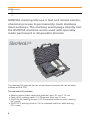
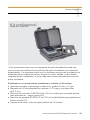
SURFOX marking kits use a fast and simple electro-
chemical process to permanently mark stainless
steel surfaces. The marking wand plugs directly into
the SURFOX machine and is used with specially
made permanent or disposable stencils.
1
Kit descriptions
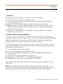
The standard kit requires the use of permanent stencils that can be easily
ordered at WALTER.
The standard kit includes:
• Marking wand, black cable and graphite insert 35 mm X 10 mm
• Pack of 20 marking pads, 5 O-Rings and Allen key 2.5 mm
• SURFOX-M marking solution 100 ml squeeze bottle for black marking
(AC mode)
• SURFOX-E etching solution 100 ml squeeze bottle for white etching
(DC mode)
Standard kit
Order no.: 54-B 080

SURFOX Marking Kits User’s Guide 3
1
Kit descriptions
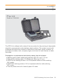
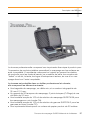
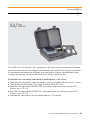
The PRO kit is offered with a stencil thermo printer for the printing of disposable
stencils to permanently mark stainless steel surfaces. The printer comes with
software that allows the creation of stencils for barcodes, serial numbers, lot
and batch numbers, text, company logos, and more to mark directly on stain-
less steel.
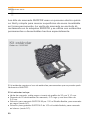
Packaged in a professional and sturdy casing, the kit includes:
• Marking wand, black cable and graphite insert 35 mm X 10 mm
• Pack of 20 marking pads, 5 O-Rings and Allen key 2.5 mm
• SURFOX-M marking solution 100 ml squeeze bottle for black marking
(AC mode)
• SURFOX-E etching solution 100 ml squeeze bottle for white etching
(DC mode)
• Thermo printer and roll of stencil paper 20 meter
Pro kit
Order no.: 54-B 081

4
2
Marking/etching procedure
Marking/etching
u Select AC mode (alternating current) for electrolytic marking (black).
u Select DC mode (direct current) for electrolytic etching (white).
With a MINI SURFOX
1. Connect the marking/etching wand to the marking/etching outlet on the
front panel.
2. Turn the selector knob to the marking/etching wand icon.
3. In the marking/etching section of the unit, select the proper mode; AC
(marking) or DC (etching) mode. Ensure the work piece is grounded.
Note: Voltage is already preset at 12 volts when marking/etching.
With a SURFOX 104
1. Connect the marking wand to the marking outlet on the front panel.
2. Press the ON button on the cleaning wand to power on the marking wand.
Ensure the work piece is grounded.
Note: Only the marking option is available with the SURFOX 104 unit. The
marking outlet is preset to AC mode. White etching is not possible with the
SURFOX 104 unit.
With a SURFOX 204
1. Connect the marking wand to the marking/etching outlet on the front panel.
2. Turn the selector knob to the marking/etching wand icon. When this mode
is selected, it automatically cuts the power to the hand wand, stops the
solution pump and the fume elimination system (if connected) from
operating. Only power is provided to the mini wand and the marking/etching
wand outlet. Ensure the work piece is grounded
3. Turn the selector knob to the marking/etching wand icon
4. In the marking/etching section of the unit, select the proper mode; AC or DC
mode.
Note: Voltage is already preset at 12 volts when marking/etching.
Warning: Ensure the SURFOX machine is turned off while proceeding to these
steps in order to avoid black marks on the part(s) to be marked.

SURFOX Marking Kits User’s Guide 5
Marking/etching procedure
Before turning on the SURFOX machine:
1. Add drops of marking or etching solution on the pad when mounted on the
marking/etching wand until saturated.
2. Apply the marking or the etching solution onto the surface to be marked or
etched using the soaked marking wand. Ensure the SURFOX unit is turned
off during this step to avoid unwanted staining of the stainless steel piece.
3. Place the stencil over the wet surface (to hold the stencil in position). Tape
can be used to hold the stencil in place.
4. Turn on the unit and rub the marking/etching wand over the top of the
stencil with a rm, but light pressure, until the marking or etching process is
completed. Make sure the part is grounded.
5. Remove the stencil.
6. Neutralize using SURFOX-N.
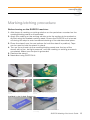
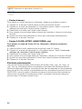
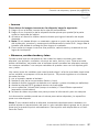
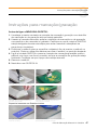
3
Marking/etching
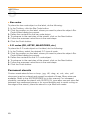
Marking with disposable stencils.
Result of black marking with disposable
stencils.
Marking with permanent stencils (U.S. only).
Marking with permanent stencils.
Result of black marking with permanent
stencils.
Result of black marking with permanent stencils
(U.S. only).
Available in the United States only

6
4
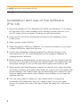
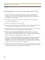
Installation and use of the software (Pro kit)
Installation and use of the software
(Pro kit)
1. Place the software CD (For Windows XP, VISTA and Windows 7X. A version
for Windows 2000 is also available upon request) supplied with the kit in
the CD reader of the computer. The auto run will then activate.
2. Unzip the ZD_2.6.42.03_Certied le and launch the installation of the
printer driver.
3. Select printer model GK420d.
4. Select the proper USB port (USB00X – X is the port number) or if you have
multiple USB ports, select the rst one.
5. Launch the installation of ZebraDesignerv2 by double clicking on the
document from the CD. ZebraDesignerv2 is the program designed for
creating stencils’ artworks.
6. Before launching ZebraDesigner for the rst time, copy the Default Label le
from the CD to the path Document\My Labels\Labels. This default label has
the proper settings for your printer and stencil paper and is easy to use.
7. When starting the ZebraDesigner program for the rst time, select the label
previously copied to the Default Label folder for a quick use of the labels with
proper settings. The Default Label can be edited (size and content) as many
times as desired and saved under different names (Make sure to keep the
extension le .ibi).
8. You may also prefer to create your own default label or change the
properties of the label every time you create a label. If this is the case,
ensure you respect the size of the stencil paper and keep the continuous
mode.

SURFOX Marking Kits User’s Guide 7
5
Label creation
Label creation and settings (Pro kit)
Creating labels with the software is self intuitive. You may also refer to help
section (F1) in the software for more details.
Quick creation of:
u Text
To place the text object on the label, do the following:
1. In the Toolbox, click the Text button.
2. Click the position on the label where you want to place the object. The Text
Wizard dialog box opens.
3. Dene the contents for the text object.
Example:
ABC Co Ltd
Operator: J. Smith
Batch #: 123456
Date: Aug. 6, 2011
4. To advance to the next step of the wizard, click the Next button.
5. Follow the onscreen instructions in the next steps.
6. Click the Finish button.
To change the position and size of the text object, select the text object and
drag the object with your mouse to the desired position. Using the Text Toolbar,
change the font for the text object. (ie.: choose Arial font, 28 point size, and
bold style).
u Pictures and logos
To place the picture object on the label, do the following:
1. From the Toolbox, click on the Picture object.
2. Click on the label where you want to place the picture. The Open dialog box
opens.
3. Browse for the picture on the hard disk, and then click the Open button.
u Rectangles
To place the rectangle object on the label, do the following:
1. In the Toolbox, click the Rectangle button.
2. Click the position on the label where you want the upper-left position of
the object to be set.

8
3. Drag in the bottom-right direction until the object size is correct.
4. The other method of positioning the rectangle object on the label is
selecting the Rectangle tool and then clicking the label. A default-sized
rectangle will appear, and you can resize it using handles around the object.
5. Note: If you want to draw a square, grab a handle on one of the rectangle
corners, simultaneously press and hold the Shift key, then resize the
rectangle. A square will be drawn.
6. To move a rectangle to a different position, select it and drag it elsewhere
on the label.
u Lines
To place the line object on the label, do the following:
1. In the Toolbox, click on the Line object.
2. Dene the line starting point by clicking the mouse at the start position.
3. Move the cursor to the end point while holding down the mouse button.
A line will be drawn from the left to right side of the label.
4. Note: To draw a vertical line, click the starting point and then drag the
cursor in the up-down direction.
u Ellipses
To place the ellipse object on the label, do the following:
1. In the Toolbox, click the ellipse button.
2. Click the position on the label where you want the upper-left position
of the object to be set.
3. Drag to the bottom-right direction until the object size is correct.
4. The other method of positioning the object on the label is selecting the
Ellipse tool and then clicking the label. A default-sized ellipse will appear,
and you can resize it using handles around the object.
5. Note: To draw a circle, grab a handle on one of the ellipse corners,
simultaneously press and hold Shift key, then resize the ellipse. A circle will
be drawn.
6. To move an ellipse to a different position, select it and drag it elsewhere
on the label.
5
Label creation

SURFOX Marking Kits User’s Guide 9
5
Label creation
u Inverse
To place the inverse object on the label, do the following:
1. In the Toolbox, click on the inverse button.
2. Click the position on the label where you want the upper-left position
of the object to be set.
3. Drag to the bottom-right direction until the object size is correct.
4. Note: To draw a square, grab a handle on one of the rectangle corners,
simultaneously press and hold the Shift key, then resize the rectangle.
A square will be drawn.
5. To move an inverse object to a different position, select it and drag it
elsewhere on the label.
u Serial, batch and lot numbers
You may want to print labels on which the data changes for each label, for
example, counter, serial numbers, date, and time. To accommodate changing
data, the software can be used to format labels using the variable elds.
Variable elds can be used with text and graphic objects.
There are several types of variables you can choose. Data, which must be
printed as a variable, is prepared at the time of printing. It can be entered in
the program in these ways:
1. by the operator from the keyboard
2. from the computer’s clock (date and time)
3. from the label design (using counters with predened starting values
and steps)
4. from the RFID tag embedded into the label
5. as output of ‘Linked eld’ or ‘Visual Basic expression’
6. database can be used to provide data for the elds
The variable data can be the same for many labels and/or specic for one
label only.
Note: If a variable denes the label, making it absolutely necessary, it is
possible to set the requirement, that a variable value must be entered in the
eld for printing to succeed. This option is available in the Text Wizard.

10
5
u Bar codes
To place the bar code object on the label, do the following:
1. In the Toolbox, click the Bar Code button.
2. Click the position on the label, where you want to place the object. Bar
Code Wizard dialog box opens.
3. Dene the contents for the bar code object.
4. To advance to the next step of the wizard, click on the Next button.
5. Follow the onscreen instructions in the next steps.
6. Click the Finish button.
u 2-D codes (QR, AZTEC, MAXICODES, etc.)
To place the 2-D code object on the label, do the following:
1. In the Toolbox, select the desired 2-D type of code.
2. Click the position on the label, where you want to place the object. Bar
Code Wizard dialog box opens.
3. Dene the contents for the 2-D code object.
4. To advance to the next step of the wizard, click on the Next button.
5. Follow the onscreen instructions in the next steps.
6. Click the Finish button.
Permanent stencils
Custom made stencils from a .bmp, .jpg, .tiff, .dwg, .ai, .cdr, .doc, .pdf
document may be ordered and reused hundreds of times. Many sizes are
available. Refer to the ACCESSORIES list in this manual. For increased
durability, neutralize the stencil with SURFOX-N, rinse after use and store at
between two cardboard pieces or for more exibility and to avoid curling on
the edge of the stencil, place the stencil in a jar lled with water.
Label creation

SURFOX Marking Kits User’s Guide 11
6
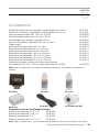
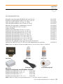
Accessories
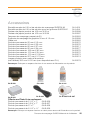
Accessories
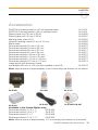
SURFOX-M marking solution 100 ml squeeze bottle 54-A 031
SURFOX-E etching solution 100 ml squeeze bottle 54-A 041
Stencil paper roll 100 mm X 20 M 54-B 086
Stencil paper roll 100 mm X 50 M 54-B 087
Marking pads, pack of 20 54-B 083
Graphite marking inserts 35 mm X 10 mm 54-B 088
Black cable 54-B 063
Permanent stencils 25 mm X 15 mm 54-B 075
Permanent stencils 54 mm X 32 mm 54-B 076
Permanent stencils 85 mm X 27 mm 54-B 071
Permanent stencils 85 mm X 54 mm 54-B 077
Permanent stencils 128 mm X 85 mm 54-B 078
Permanent stencils 170 mm X 54 mm 54-B 072
Permanent stencils 170 mm X 108 mm 54-B 073
Permanent stencils 257 mm X 170 mm 54-B 074
Large stencil with aluminum frame
(not exible) 355 mm X 155 mm (Not available in the US) 54-B 079
Note: Allow a space of approximately 4 mm surrounding the artwork on the stencil.
54-B 088 54-A 031 54-A 041
54-B 083 54-B 063 54-B 086/54-B 087
Available in the United States only:
Permanent stencil 2 1/2” x 7” 54-B 066
Permanent stencil 3 3/4” x 7” 54-B 067
Permanent stencil 5” x 7” 54-B 068
Permanent stencil 8 1/2” x 11” 54-B 069
Note: Allow a space of approximately 1/2” surrounding the artwork on the stencil.

12
7
Troubleshooting
Troubleshooting
u Printer/Software
Q: Stencil paper is coming out of the printer 1/4”, then back in without printing.
A: Ensure the label sensor located below the print head when opening the
printer (lift the stencil paper up to nd it) is properly covered with the original
glue/tape from manufacturing. If not, add a piece of electric tape to cover it.
Q: Stencil paper printing, then unrolling out of the printer continuously.
A: Ensure the printer settings are properly adjusted to continuous paper feed.
Go to software program FILE, select PRINTER SETTINGS and ADVANCE
SET-UP tab. Under TRACKING MODE, select CONTINUOUS.
u Cleaning the print head
Let the print head to cool for a minute, and then use a new cleaning pen to
swab the dark line on the print head cleaning from the center to the outside
edges of the print head. Avoid using a used pen to avoid contamination from
previous head cleaning. This cleaning should be performed after each roll of
stencil paper.

SURFOX Marking Kits User’s Guide 13
8
Warranty and service
Warranty and service
All WALTER SURFOX Marking Kits, cleaning systems and accessories are in-
spected and tested before shipment and are warranted to be free from any defect
in material and faulty workmanship. Should any malfunction occur within six (6)
months from the date of original purchase, return the complete system prepaid with
proof of purchase, to the nearest WALTER Factory or Authorized Service Center.
If an examination shows that the malfunction was caused by defective material or
faulty workmanship, WALTER will repair (or at our option, replace the unit) with-
out charge. This warranty does not apply when; normal maintenance is required,
repairs or replacements have been made or were attempted by anyone other than
WALTER authorized service personnel, and does not cover any damage caused by
accidents, modications, use of improper accessories, abuse or misuse, which also
includes overloading the tool beyond its rated capacity as well as its continued use
after partial failure. No other warranty, written or verbal, is authorized.
In no event shall WALTER be liable for any indirect, incidental or consequential dam-
ages from the sale of the product. This disclaimer applies both during and after the
term of this warranty.
This warranty gives you specic rights. The provisions contained in this warranty are
not intended to limit, modify, take away from, disclaim or exclude any warranties set
forth in any Provincial or State legislation. To the extent required by law, the provi-
sions in any Provincial, State or Federal legislation with respect to warranties take
precedence over the provisions in this warranty.


Trousses de marquage SURFOX Manuel de l’utilisateur 15
Table des matières
Table des matières
1 Description de la trousse 16
Trousse standard 16
Trousse professionnelle 17
2 Marquage et gravure 18
Avec un MINI SURFOX 18
Avec un SURFOX 104 18
Avec un SURFOX 204 18
3 Procédure de marquage et gravure 19
4 Installation et utilisation du logiciel
(Trousse Pro) 20
5 Création d’étiquettes et paramètres
(Trousse Pro) 21
Création rapide de texte 21
Création rapide d’images et de logos 21
Création rapide de rectangles 21
Création rapide de lignes 22
Création rapide d’ellipses 22
Création rapide d’inverses 23
Création rapide de numéros de série, de numéros
de “batch” et numéros de lot 23
Création rapide de codes à barres 24
Création rapide de codes 2-D 24
Pochoirs permanents 24
6 Accessoires 25
7 Résolutions de problèmes 26
8 Garantie et service 27

16
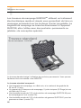
Les trousses de marquage SURFOXMC utilisent un traitement
électrochimique rapide et simple vous permettant de faire un
marquage permanent sur les surfaces d’acier inoxydable. La
baguette de marquage se branche directement à l’appareil
SURFOX; elle s’utilise avec des pochoirs – permanents ou
jetables – de conception spéciale.
1
Description des trousses
La trousse standard exige l’utilisation de pochoirs permanents. Vous pouvez
facilement les commander chez WALTER.
La trousse standard comprend :
• Une baguette de marquage, un câble noir, et un embout de graphite de
35 mm X 10 mm.
• Un paquet de 20 tampons de marquage, 5 joints toriques (O-Rings) et une
clé Allen de 2,5 mm.
• Une bouteille souple de 100 ml de solution de marquage SURFOX-M pour
les marquages en noir (mode CA).
• Une bouteille souple de 100 ml de solution de gravure SURFOX-E pour les
gravures en blanc (mode CC).
Trousse standard
No de commande : 54-B 080

Trousses de marquage SURFOX Manuel de l’utilisateur 17
1
Description des trousses
La trousse professionnelle comprend une imprimante thermique à pochoir pour
l’impression de pochoirs jetables permettant le marquage sur les surfaces en
acier inoxydable. L’imprimante comprend un logiciel qui permet la création
de pochoirs pour les codes à barres, les numéros de série, les numéros de
“batch” et de lot, le texte, les logos d’entreprise et autres, en vue d’un mar-
quage direct sur l’acier inoxydable.
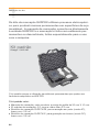
La trousse est emballée dans un boîtier professionnel et robuste;
elle comprend les éléments suivants :
• Une baguette de marquage, un câble noir, et un embout de graphite de
35 mm X 10 mm.
• Un paquet de 20 tampons de marquage, 5 joints toriques (O-Rings) et une
clé Allen de 2,5 mm.
• Une bouteille souple de 100 ml de solution de marquage SURFOX-M pour
les marquages en noir (mode CA).
• Une bouteille souple de 100 ml de solution de gravure SURFOX-E pour les
gravures en blanc (mode CC).
• Une imprimante thermique et un rouleau de papier pochoir de 20 mètres.
Trousse Pro
No de commande : 54-B 081

18
2
Marquage et gravure
Marquage et gravure
u Sélectionnez le mode CA (courant alternatif) pour le marquage électrolytique (noir).
u Sélectionnez le mode CC (courant continu) pour la gravure électrolytique (blanc).
En utilisant un MINI SURFOX
1. Branchez la baguette de marquage/gravure dans la sortie de marquage/gravure
située sur la partie avant de l’appareil.
2. Réglez le bouton de contrôle sur l’icône de la baguette de marquage/gravure.
3. Dans la section de marquage et gravure de l’appareil, sélectionnez le mode de
courant approprié : CA pour le marquage; CC pour la gravure. Assurez-vous que
la pièce sur laquelle vous travaillez est mise à la terre
Remarque : La tension électrique est préréglée à 12 volts pour le marquage
et la gravure.
Utilisation avec un SURFOX 104
1. Branchez la baguette de marquage à la sortie de marquage du panneau avant
2. Pressez le bouton EN MARCHE (ON) de la baguette de nettoyage pour activer
la baguette de marquage. Assurez-vous que la pièce sur laquelle vous travaillez
est mise à la terre.
Remarque : L’appareil SURFOX 104 n’offre que l’option de marquage. La sortie de
marquage est préréglée au mode CA. La gravure en blanc est impossible avec cet
appareil.
Utilisation avec un SURFOX 204
1. Branchez la baguette de marquage dans la sortie de marquage/gravure située
sur la partie avant de l’appareil.
2. Réglez le bouton de contrôle sur l’icône de la baguette de marquage/gravure.
Lorsque ce mode est sélectionné, le courant vers la baguette à main est
automatiquement coupé, la pompe à solution s’arrête et le fonctionnement du
système d’élimination des fumées (s’il est en fonction) est interrompu. Seules
les sorties prévues pour la mini-baguette ou la baguette de marquage/gravure
reçoivent du courant. Assurez-vous que la pièce sur laquelle vous travaillez est
mise à la terre.
3. Réglez le bouton de contrôle à l’icône de la baguette de marquage/gravure.
4. Dans la section de marquage/gravure de l’appareil, sélectionnez le mode de
courant approprié; CA ou CC.
Remarque : La tension est préréglée à 12 volts pour le marquage/gravure.
Avertissement : Assurez-vous que l’appareil SURFOX est à l’arrêt lorsque vous
réalisez ces étapes an d’éviter que des marques noires apparaissent sur la pièce
qu’il faut marquer.
A página está carregando...
A página está carregando...
A página está carregando...
A página está carregando...
A página está carregando...
A página está carregando...
A página está carregando...
A página está carregando...
A página está carregando...
A página está carregando...
A página está carregando...
A página está carregando...
A página está carregando...
A página está carregando...
A página está carregando...
A página está carregando...
A página está carregando...
A página está carregando...
A página está carregando...
A página está carregando...
A página está carregando...
A página está carregando...
A página está carregando...
A página está carregando...
A página está carregando...
A página está carregando...
A página está carregando...
A página está carregando...
A página está carregando...
A página está carregando...
A página está carregando...
A página está carregando...
A página está carregando...
A página está carregando...
A página está carregando...
A página está carregando...
A página está carregando...
A página está carregando...
-
 1
1
-
 2
2
-
 3
3
-
 4
4
-
 5
5
-
 6
6
-
 7
7
-
 8
8
-
 9
9
-
 10
10
-
 11
11
-
 12
12
-
 13
13
-
 14
14
-
 15
15
-
 16
16
-
 17
17
-
 18
18
-
 19
19
-
 20
20
-
 21
21
-
 22
22
-
 23
23
-
 24
24
-
 25
25
-
 26
26
-
 27
27
-
 28
28
-
 29
29
-
 30
30
-
 31
31
-
 32
32
-
 33
33
-
 34
34
-
 35
35
-
 36
36
-
 37
37
-
 38
38
-
 39
39
-
 40
40
-
 41
41
-
 42
42
-
 43
43
-
 44
44
-
 45
45
-
 46
46
-
 47
47
-
 48
48
-
 49
49
-
 50
50
-
 51
51
-
 52
52
-
 53
53
-
 54
54
-
 55
55
-
 56
56
-
 57
57
-
 58
58


Walter SURFOX PRO Kit Manual do proprietário
- Tipo
- Manual do proprietário
- Este manual também é adequado para
em outras línguas
Artigos relacionados
Outros documentos
-
Barbie W1598 Instruções de operação
-
 BAUKER NLCO1 Manual do proprietário
-
Lexibook CR800 Manual do usuário
-
-
Black & Decker CI500 Manual do usuário
-
VIDU DTX-VI91012 Manual do usuário
-
Titan PowrLiner 4500 Manual do usuário
-
Estate TUD8700SQ Manual do usuário
-
Focal Arche Manual do usuário
