
EC10 & EX16 Quick Start Guide
www.esslsecurity.com
User Manual

E C 10 & E X 16 Q uick S ta rt G uide
B utton-controlled
R S 485
T C P /I P or R S 485
W ie ga nd/R S 48 5
E C 10 E leva tor C ontrol P a ne l
E X -16 F loor E xpa ns ion B oard
O R
F ingerprint
R e a de r
R F ID R ea de r
E le va tor F loor B uttons
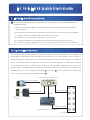
T he E C 10 pre vents una uthoriz ed ele vator-us e rs from a c c e s s ing pre-defined res tricted floors in
the building. T he E C 10 (E leva tor C ontrol panel) c ontrols acce s s up to 10 floors . Als o a va ila ble is
the E X 16 ( E le vator F loor E xpa ns ion boa rd) w hich a llows f or a cces s c ontrol of up to 1 6 a dditional
floors . A maximum three E X 16 boa rds c a n be da is y-c ha ined toge the r a nd collec tively control
a cces s of up to 58 floors . In order to gain a c c es s to a des ired floor, a uthoriz e d us ers mus t firs t
pres e nt e ithe r a va lid finge rprint a nd/or R F ID ca rd when entering the eleva tor. F or e xa mple, if a n
a uthorized us er has acce s s rights to only floor a nd floor , the eleva tor will not move if that
s a me u s e r p res s e s t he e le va tor button for floor .
3
4
10
2.S ys tem Introductions
1.Ins ta lla tion P reca utions
B utton-controlled
P ay a tte ntion to the f ollowing s a fe ty i tems . M is -opera tions m a y c aus e h uma n d a nger o r
equipment fa ults :
1)B e fore i ns ta lla tion c ompletes , d o not power o n the e quipment or p erform o pe ra tions
w ith e lectricity.
2) U s e d edica ted e le va tor e therne t ca ble t o c onnec t the e le va tor c ontroller a nd c ompute r.
U s e 2 pin c ontrolle r c a ble f or the p res s b utton on e ach floor.
3) I ns tall the c a rd rea der w ith a h e ight of 1 . 2 t o 1 . 4 m ete rs .
4) I ns ta ll the e leva tor m a in c ontroller a nd e xpa ns ion boa rd on the e le va tor lift ca r.
5) I ns ta ll the e merge ncy b utton in the m a na ge me nt ce nter o r u nde r the e le va tor b utton.
.

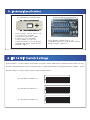
E C 10Technica l S pecifica tion
3.Technical S pecifica tions
E X 16Tec hnica l S pe cifica tion
F loor button control re la ys :10
C a rd c a pa c ity: 3 0 , 000
F inge rprint ca pa city: 3 , 00 0
E vent c a pac ity: 1 0 0 , 00 0
P ower s upply: 12V DC 1A
C ommunica tion: T C P /IP, R s 485
S upporte d floor e xpa ns ion
boa rd: 3pcs
F loor button control re la ys :16
C ommunica tion to E C 10 pa ne l: R S 485
P owe r s upply: 1 2V D C 1 A
R S 485 D evic e a ddres s 2
4.E X 16 DIP S witch S ettings
DIP s witches 2 -4 a re u s ed to s e t e a ch E X 16 F loor E xtens ion B oard's u nique d evice a ddre s s u s ing
R S 485 c ommunica tion. P le a s e k eep the E X 16 p owe red o ff before s etting the d e vice a ddres s . E a ch
de vic e a ddres s n eeds t o be u nique. S ee e xa mple b e low:
R S 485 D evic e a ddres s 3
R S 485 D evic e a ddres s 4
1 2 3 4
O
5 6 7 8
K
E
N
1 2 3 4
O
5 6 7 8
K
E
N
1 2 3 4
O
5 6 7 8
K
E
N

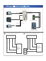
6.W iring a n E leva tor C ontrol S ys tem
Ty pic a l E lev a tor W ir ing D ia gr a m E C 10/E C 16 E lev a tor W ir in g D ia gr a m
G ND
L E D-
L E D+
E leva tor s ys te m
E le va tor B uttons c ontrolled line
E leva tor
B uttons
C ontrolle d
P a ne l
G ND
L E D-
L E D+
NC
C O M
NO
E leva tor s ys te m
E leva tor B uttons c ontrolled line
E leva tor
B uttons
C ontrolle d
P a ne l
E leva tor C ontrol P a nel
R S 485 E X T-
F loor E xpans ion B oa rd
F inge rprint R e a der
DC 1 2V
W iegand R e a der
T C P /IP connect with P C
R S 485- R S 485+
R S 485 E X T +

18# O utput
17# O utput
16# O utput
15# O utput
14# O utput
13# O utput
12# O utput
11 #O utput
DC 12V
26# O utput
25# O utput
24# O utput
22# O utput
21# O utput
20# O utput
19# O utput
23# O utput
12V O utput
R S 485
NC
C O M
NO
NC
C O M
NO
NC
C O M
NO
NC
C O M
NO
NC
C O M
NO
NC
C O M
NO
NC
C O M
NO
NC
C O M
NO
G ND
S TAT
+12V
G ND
A U X O U T 8 A U X O U T 1 6
A U X O U T 7 A U X O U T 1 5
A U X O U T 6 A U X O U T 1 4
A U X O U T 5 A U X O U T 1 3
A U X O U T 4 A U X O U T 1 2
A U X O U T 3 A U X O U T 11
A U X O U T 2 A U X O U T 1 0
A U X O U T 1
I N D
P O W E R
E X T
NO
C O M
NC
NO
C O M
NC
NO
C O M
NC
NO
C O M
NC
NO
C O M
NC
NO
C O M
NC
NO
C O M
NC
NO
C O M
NC
+12V
G ND
485-
485+
E X -16
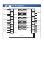
7. E X 16 E leva tor W iring Dia gra m
B a c kup
O utput

1) The backup input is reserved for the elevator control system.
2) Fire linkage and emergency button function require no software settings. These functions are available when the hardware is installed.
3) GPRS, WIFI and functions marked by * are optional. If these functions are required, contact our business representatives or pre-sale technical support.
Notes:
4) "# " indicates floor , "1# output"indicates that it is connected to the first floor button, the first expansion board is connected to the 11th floor button.
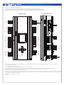
8.EC10 Wiring Terminals C onnec tion
Data_Tx-
Data_Tx+
GND
Data_RxTx-
Data_RxTx+
Shield
+12V
GND
Shield
AC Fail
Battery Fail
VCC 12V
GND
D0
D1
Shield
LED_G
LED_R
BEEP
Hold
Card_present
VCC 12V
GND
D0
D1
Shield
LED_G
LED_R
BEEP
Hold
Card_present
Card_present
Hold
BEEP
LED_R
LED_G
Shield
D1
D0
GND
VCC 12V
Card_present
Hold
BEEP
LED_R
LED_G
Shield
D1
D0
GND
VCC 12V
NO
COM
NC
NO
COM
NC
NO
COM
NC
NO
COM
NC
NC
COM
NO
NC
COM
NO
NC
COM
NO
NC
COM
NO
3# Output
2# Output
1# Output
5# Output
4# Output
8# Output
12V Power Input
Shield Wire
AC Fail Detection
12V Power Output
12V Power Out
12V Power Output
12V Power Output
Wiegand Input
Wiegand Input
Wiegand Input
Wiegand Input
Shield Wire
Sheild Wire
Shield Wire
Shield Wire
Green
Green
Red
Red
Red
Red
Green
Green
Beep
Beep
Beep
Beep
Controlled Reader Hold
Controlled Reader Hold
Controlled Reader Hold
Card Present
Card Present
Card Present
Card Present
{
{
{
{
{
{
{
{
{
{
{
Shield Wire
}
}
}
}
}
}
}
}
RS 422 Send
}
Extension Board
or SR 485 Reader
}
Controlled Reader Hold
Output
Output
Output
*
*
**
*
*
*
RS-485 EXT WIEGAND 3IN5 IN6 OUT5 OUT6 WIEGAND 4IN7 IN8 OUT7 OUT81
3
1
3
1
2
1
2
1
10
1
3
1
3
1
212
1
10
1
6
WIEGAND 1IN1 IN2OUT1 OUT2 WIEGAND 2IN3 IN4 OUT3 OUT4
13
POWER
15110 1 2 1 2 1 313110 1 2 1 2 13
Reset
Fr ont View Fr ont Side V iew
RS-232
IN9 OUT9
IN12IN11
IN10 OUT10 RS-485
1313
1 21 21 21 2
1 4
1 4
Output
*
*
*
*
*
Shield
RS 485-
RS 485+
GND
TCP/IP
Analog_input
GND
Analog_input
GND
NO
COM
NC
NO
COM
NC
TCP/IP Comm.
Fire Linkage Input
Emergency button Input
9# Output
Shield Wire
RS485 Comm.
RS485 Ground
*
*
*
*
*
}}
Battery Fail Detection
6# Output
7# Output
10# Output
1. Open the elevator press button panel when connecting to the elevator button. Ask the supplier to provide the floor button control circuit. If the supplier can not provide the circuit, exclude the incorrect circuit one
Notice:
by one and ensure the correct connections.
2 . EC10 connects to the computer using TCP/IP or RS485.
4 . EC10 controls access up to 10 , EX16 floors controls access up to 16 floors. An EC10 carries a maximum of 3 expansion boards. Total 58 floors can be controlled when combining EC10 with EX16.
3. EC10 supports ZK fingerprint readers (model FR1200) and RFID card readers (model KR series).
5. The RS485 device address of the fingerprint reader (model FR1200) must be 1. The RS485 device address of the EX16 floor extension board must start from 2.
6. Wiegand reader can connect to the elevator main controller Wiegand 1#~ 4#.
7. IN9 functions as fire linkage signal input. When fire linkage signal works, elevator control system stops working and the elevator retains to original status. (Fire linkage must be passive dry contact signal)
8. IN10 functions as an emergency button. When it is pressed, the whole elevator is not controlled by elevator controller. At this moment, up and down buttons are available. When the emergency button is
not pressed, the elevator retains to the original status.
1
2
3
4
7
5
6
8
9
10
9. ~ Output terminals connect to floor press button.
110

#24, Shambavi Building, 23rd Main, Marenahalli, JP Nagar 2nd Phase, Bengaluru - 560078
Phone : 91-8026090500 | Email : sales@esslsecurity.com
www.esslsecurity.com
-
 1
1
-
 2
2
-
 3
3
-
 4
4
-
 5
5
-
 6
6
-
 7
7


em outros idiomas
- English: eSSL EC10 User manual
Outros documentos
-
 Novexx XPA 93x Manual do usuário
-
Hitachi DH 38YE2 Safety Instructions And Instruction Manual
-
Gemini Musical Instrument EX-26 Manual do usuário
-
Schlage MT15-485 Guia de instalação
-
ALLEGION SM10 Installation Instructions & User Manual
-
Grandstream GDS3710 Quick Installation Guide
-
Grandstream GDS3705 Quick Installation Guide
-
GE ATS1192 Manual do proprietário
-
Yamaha 430 Manual do proprietário
