Klip Xtreme KPM-610B Manual do proprietário
- Categoria
- Montagens de projetor
- Tipo
- Manual do proprietário

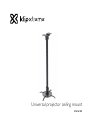
KPM-610B
Universal projector ceiling mount

English
Installation Manual
Thank you for choosing Klip Xtreme’s Universal Projector Ceiling Mount. The KPM-610B has been
designed to securely attach projectors or any other presentation device to the ceiling.
For support and to nd out more about this and other new and exciting products recently
released, we invite you to visit us at www.klipxtreme.com.
INSTALLATION INSTRUCTIONS
Contents
Warning Statements
Installation Tools
Parts List
Features
Installing the Projector Mount
Wood Stud Installation
Concrete Ceiling Installation
Attaching the Projector Plate
Technical Specications
Weight Limit
Maximum Projector Weight: 33 lb
THE CEILING STRUCTURE MUST BE CAPABLE OF SUPPORTING AT LEAST THREE TIMES THE WEIGHT
OFTHE PROJECTOR. OTHERWISE, THE CEILING STRUCTURE MUST BE REINFORCED.

Warning Statements
• Prior to installaling this product, you must read all instructions thorougly. Keep these installation
instructions in an easily accessible location for future reference.
• Proper installation procedure by a qualied service technician must be followed, as outlined in
these installation instructions. Failure to do so could result in property damage, serious personal
injury, or even death.
• Safety measures must be practiced at all times during the assembly of this product. Use proper
safety equipment and tools for the assembly procedure to prevent personal injury.
• Klip Xtreme does not warrant against damage caused by the use of any Klip Xtreme mounts for
purposes other than those for which it was designed or damage caused by unauthorized
attachments or modications, and is not responsible for any damages, claims, demands, suits,
actions or causes of action of whatever kind resulting from, arising out of or in any manner
relating to any such use, attachments or modications.
• At least two qualied people should perform the assembly procedure. Personal injury and/or
property damage can result from dropping or mishandling the projector.
• If mounting to wall studs or ceiling studs, make sure that the mounting screws are anchored into
the center of the wall studs or ceiling studs. Use of an edge-to-edge stud nder is recommended.
• Be aware of the mounting environment. If drilling and/or cutting into the mounting surface,
always make sure that there are no electrical wires in wall. Cutting or drilling into an electrical line
may cause serious personal injury.
• Make sure there are no water or natural gas lines inside the wall where the mount is to be
located. Cutting or drilling into a water or gas line may cause severe property damage or personal
injury.

1 3 4 5
9876
2
• This product is intended for indoor use only. Use of this product outdoors could lead to product
failure and/or serious personal injury.
• Do not install near sources of high heat. Do not install on a structure that is prone to vibration,
movement or chance of impact.
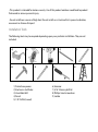
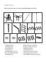
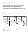
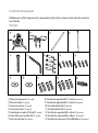
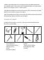
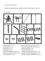
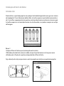
Installation Tools
The following tools may be required depending upon your particular installation. They are not
included.
1) Protective eyewear 6) Hammer
2) Electronic stud nder 7) 5/16˝ Masonry drill bit
3) Hand-held drill 8) Phillips head screwdriver
4) Pencil 9) Ladder
5) 1/8˝ Drill bit (wood)

1
5
10 11 12 13 14
3
7
4
89
2
6
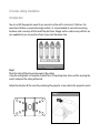
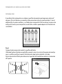
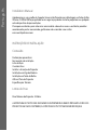
1) Projector plate (Qty 1)
2) Ceiling plate (Qty 1)
3) Outside pole (Qty 1)
4) Inner pole (Qty 1)
5) ST 6.3x60 wood screw (Qty 4)
6) M5 security Allen wrench (Qty 1)
7) Mount legs (Qty 4)
8) M4 x 12mm security screw (Qty 4)
9) M5 x 12mm security screw (Qty 4)
10) M6 at washer (Qty 4)
11) M5 at washer (Qty 4)
12) M6 x 45mm security screw (Qty 2)
13) M6 x 40mm security screw (Qty 2)
14) Ø6.3xØ8x40mm expansion screw (Qty 4)
Package Contents
Make sure none of these parts are missing or damaged before beginning installation.

1
3
5
4
2
360°
+
-15 °
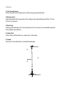
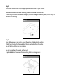
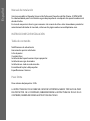
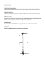
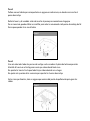
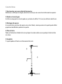
Features
1) Tool-free adjustment
Precise yaw, pitch and roll adjustments without requiring specialized tools.
2) Mounting slots
Adjustable length from the projector to the ceiling can be adjusted between 850 to 1215 mm
(in 50 mm increments).
3) Mount legs
Featuring adjustable legs with several mounting slots, this mount can accommodate projectors
with multiple mount patterns.
4) Ceiling Plate
Can be easily installed either on a wood stud or solid ceiling.
5) Coupler
The mount can be attached to a standard threaded pipe.

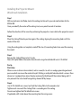
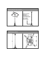
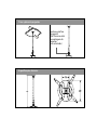
Installing the Projector Mount
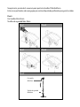
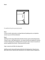
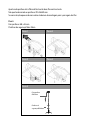
Wood stud installation
Step 1
With an electronic stud nder, locate the ceiling stud closest to your desired location for the
KPM-610B.
Once you identify the center of the ceiling stud, use a pencil to mark its location.
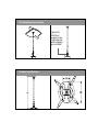
Follow the direction of the arrow for positioning the projector screen relative the projector mount.
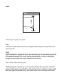
Step 2
Place the Ceiling Plate into position against the ceiling, aligning the mounting holes with the
center of the stud.
Using the ceiling plate as a template, mark o the two (2) mounting holes to be used for securing
the mount.
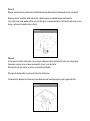
Step 3
Remove the Ceiling Plate and set it aside.
Next, drill a pilot hole in the center of each mark using a hand held drill and a 1/8˝ drill bit.
Pro tip
Pilot Holes
When a screw is driven into a material, such as wood, it can act as a wedge, generating outward
pressure which can cause the material to split. Drilling a small pilot hole into which a screw is then
driven, less ‘wedging’ takes place, thereby reducing the likelihood of the material being split. It
also prevents the screw head from getting sheared o by torque.
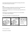
Step 4
Use (4) ST6.3x8x40 mm screws to attach the Ceiling Plate to the wooden stud.
Tighten each screw until the Ceiling Plate is secured against the ceiling.
Do not over tighten the ST6.3x8x40 mm screws.
If applicable, drill a hole above the mounting hole for wiring access.

Step 1 Step 2
Step 3
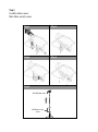
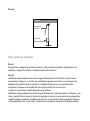
Step 5
Step 4
Step 5
Two M6 x 45mm screws
M6 x 40mm security screws
Two M6x45mm screws
M6x40mm security
screws

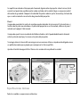
Step 1
Example wedge anchors and masonry bit
Not included
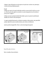
Concrete ceiling installation
Introduction
You can install the projector mount to any concrete surface with a minimum 6˝ thickness. For
concrete installation, use concrete wedge anchors (¼˝ recommended) to secure the mounting
hardware, and a masonry drill bit to drill the pilot holes. Wedge anchors and masonry drill bits are
not supplied, but you can purchase them at your local hardware store.
Step 1
Place the Ceiling Plate into position against the ceiling.
Using the ceiling plate as a template, mark o four (4) mounting holes to be used for securing the
mount, and place the ceiling plate aside.
Follow the direction of the arrow for positioning the projector screen relative the projector mount.

Step 2
Step 3
Step 2
Drill a hole at each mark using the appropriate masonry bit for your anchor.
Remove nut and washer before inserting a concrete anchor into each hole.
If necessary, a hammer can be used to lightly tap each wedge anchor into place, so that they are
ush with the ceiling.
Step 3
Once all the anchors are in place, move the ceiling plate back into position.
Attach the nut onto the threaded shaft that is protruding from the ceiling.
Do not tighten until all nuts are in place.
Do not over tighten the wedge anchor nuts.
If applicable, drill a hole above the mounting hole for wiring access.

Step 4
Attaching the projector plate
Step 1
Thread the selected hardware into each mounting point of the projector, making sure to use the
correct screw size.
Step 2
Identify the projector’s approximate front-to-back center of gravity. Place your hands on each side
of the projector and gently lift it an inch from the surface on which it is resting. Carefully adjust
your grip on the projector until it seems balanced from front-to-back.
Make a mental note of center of gravity.
Identify the projector’s approximate side-to-side center of gravity. Place your hands on the front
and back of the projector and gently lift it an inch from the surface on which it is resting. Carefully
adjust your grip on the projector until it seems balanced from side-to-side. Make a mental note
Step 4
Two M6x45mm screws
M6x40mm security
screws

Step 1 Step 2 Step 3
Side-to-side
Center of gravity
Front-to-back
Center of gravity
Sliding M6
Square Nut
of center of gravity. Place the Projector Assembly on top of the mounting legs with the center as
close as possible to the projector’s center of gravity.
Step 3
Verify that the mounting legs are all adjusted at the same level. Otherwise, if the height of mount
legs do not match or if the projector plate is not level, go to step 2 on page 9.
Verify that the supplied sliding M6 square nut in the mount leg is properly aligned with the slot on
the Projector Plate.
If the M6 square nut cannot be aligned with any nearby slot, you can use any thin implement,
such as a toothpick, to nudge it into alignment.
Tighten the M6 x 10mm hexagon screw in the projector collar assembly.
Technical Specications
All measurements are in millimeters.

Attaching the projector plate
Technical specications
Tighten the
M6x10mm
hexagon screw
in the projector
collar assembly
(pre-installed)

Español
Manual de instalación
Gracias por preferir el Soporte Universal de Techo para Proyector de Klip Xtreme. El KPM-610B
ha sido concebido para la instalación segura de proyectores o cualquier otro aparato audiovisual
desde el techo.
En caso de requerir asistencia y para conocer más acerca de éste u otros innovadores productos
recientemente lanzados al mercado, visite nuestra página web en www.klipxtreme.com.
INSTRUCCIONES DE INSTALACIÓN
Tabla de contenido
Noticaciones de advertencia
Herramientas para la instalación
Lista de piezas
Características
Instalación del soporte universal para proyector
Instalación en vigas de madera
Instalación en cielo raso de concreto
Ensamble de la placa del proyector
Especicaciones técnicas
Peso límite
Peso máximo del proyector: 33 lb
LA ESTRUCTURA DEL TECHO DEBE SER CAPAZ DE SOPORTAR AL MENOS TRES VECES EL PESO
DEL PROYECTOR. DE LO CONTRARIO, DEBERÁ REFORZAR LA ESTRUCTURA DEL TECHO. DE LO
CONTRARIO, DEBERÁ REFORZAR LA ESTRUCTURA DEL TECHO.

Noticaciones de advertencia
• Antes de proceder con la instalación, lea todo el manual detenidamente. Mantenga estas
intrucciones en un lugar accesible , con el n de utilizarlas como referencia en el futuro.
• El proceso de instalación debe estar a cargo de técnicos calicados, según se indica en esta
guía. De no observar tales instrucciones, corre el riesgo de sufrir daños materiales o lesiones que
pueden resultar fatales.
• Debe practicar todas las medidas de seguridad pertinentes durante todo el proceso de
en-samblaje del producto. Con el objeto de evitar lesiones físicas, utilice herramientas y equipos
de protección adecuados para ensamblar el producto.
• Klip Xtreme no se hace responsable de cualquier daño ocasionado por el uso indebido de
un soporte Klip Xtreme, o de cualquier daño producto de una conexión o modicación no
autorizada, como tampoco asume responsabilidad alguna por perjuicios, reclamos, demandas,
acciones judiciales o encausamientos de cualquier índole que surjan, se originen, o de cualquier
otra forma, estén vinculados con dicha utilización, conexión o modicación.
• El proceso de ensamblaje debe ser ejecutado al menos por dos personas capacitadas. El manejo
inadecuado o el montaje defectuoso de la unidad puede resultar en lesiones físicas o daños
materiales.
• Si monta el soporte en vigas de madera ubicadas en la pared o en el techo, debe asegurarse de
jar bien los tornillos en el centro de los montantes pertenecientes a la estructura seleccionada.
Se recomienda utilizar un detector de montantes que determine la ubicación de los bordes de
cada viga.
• Preste atención a todos los elementos existentes en el punto de instalación. Antes de perforar
o cortar cualquier supercie, siempre debe cerciorarse de que no existan cables eléctricos por
detrás del panel escogido para la instalación. Si corta o perfora un cable eléctrico, corre el riesgo
de sufrir lesiones de gravedad.
• Debe comprobar de que no pasan tuberías de agua o gas natural por el interior de las paredes en

1) Gafas protectoras 6) Martillo
2) Detector electrónico de vigas 7) Broca para mampostería de 5/16”
3) Taladro manual 8) Destornillador Philips
4) Lápiz 9) Escalera
5) Broca (para madera) de 1/8˝
1 3 4 5
9876
2
donde piensa instalar el soporte. Si corta o perfora tuberías de agua o gas natural, corre el riesgo
de sufrir lesiones de gravedad.
• Este producto ha sido concebido para uso en ambientes interiores solamente. Si lo utiliza en
exteriores, el soporte puede fallar y provocar lesiones de gravedad a las personas.
• No instale este producto cerca de una fuente generadora de calor. No instale el producto en una
estructura inestable o donde pueda quedar expuesto a vibraciones o impactos.
Herramientas para la instalación
Las herramientas en la lista son las que necesitaría para su instalación, lo cual depende de
las características especícas del proyecto. El kit no incluye ninguna de las herramientas mencionadas
a continuación.

1
5
10 11 12 13
3
7
4
89
2
6
14
1) Placa para proyector (1 unidad)
2) Placa de techo (1 unidad)
3) Columna exterior (1 unidad)
4) Columna interior (1 unidad)
5) Tornillo para madera ST6 3x60 (1 unidad)
6) Llave Allen para tornillos M5 (1 unidad)
7) Patas de montaje (4 unidades)
8) Tornillo de seguridad M4 x 12mm (4 unidades)
9) Tornillo de seguridad M5 x 15mm (4 unidades)
10) Arandela plana M6 (4 unidades)
11) Arandela plana M5 (4 unidades)
12) Tornillo de seguridad M6 x 45mm (2 unidades)
13) Tornillo de seguridad M6 x 40mm (2 unidades)
14) Tornillos de expansión Ø6.3xØ8x40mm (4 unidades)
Contenido del paquete
Verique que no falta ninguna pieza y que además todas están en buen estado antes de comenzar
la instalación.
Herrajes

Características
1) Ajuste fácil sin herramientas
El ajuste preciso del ángulo de inclinación, altura y giro se logra sin herramientas especializadas.
2) Ranuras de montaje
Separación ajustable entre el proyector y el techo de 850 a 1215 mm (en incrementos de 50 mm).
3) Patas de montaje
El soporte, al contar con patas ranuradas para ajustar independientemente la longitud de cada una,
permite acomodar proyectores con diversas conguraciones de montaje.
4) Placa de techo
Se puede instalar con toda faciliad en una viga de madera o en un cielo raso de concreto.
5) Acoplador
El soporte se puede empalmar a un tubo de rosca convencional.
1
3
5
4
2
360°
+
-15 °

Instalación del soporte para proyector
Instalación en vigas de madera
Paso 1
Con un detector de vigas, localice el montante de techo más cercano al punto donde desea
instalar el KPM-610B.
Una vez identicado el centro del montante de techo, marque su ubicación con un lápiz.
Siga la dirección de la echa para determinar la posición de la pantalla en relación a la ubicación
del soporte.
Paso 2
Coloque la placa de techo en posición sobre la supercie, alineando los agujeros de montaje con
el centro de la viga.
Utilizando la placa de techo como plantilla, proceda a marcar los dos (2) agujeros de montaje que
va a utilizar para jar el soporte.
Paso 3
Saque la placa de techo y déjela a un lado.
A continuación, perfore un agujero en el centro de cada marca con un taladro manual y una broca
de 1/8˝.
Consejo práctico
Agujero piloto
Cuando se introduce un tornillo en un material como la madera, puede producir el efecto de una
cuña, generando una presión hacia los lados capaz de partir el material. Al abrir un agujero piloto
en el punto adonde se va a colocar un tornillo, se reduce el efecto de “cuña” y la posibilidad de
partir el material. También evita que se destruya la cabeza del tornillo al aplicar fuerza.
Paso 4
Con los cuatro (4) tornillos ST6.3x8x40 mm, je la placa contra el montante de madera en el
techo.
Apriete cada tornillo hasta que la placa quede bien asegurada contra el techo.

Paso 1 Paso 2
Paso 3
Paso 5
Paso 4
No ejerza más presión de la necesaria para apretar los tornillos ST6.3x8x40 mm.
En los casos pertinentes, abra un agujero por encima del punto de perforación para guiar los cables.
Paso 5
Dos tornillos M6 x 45mm
Tornillos de seguridad M6 x 40mm
Dos tornillos
M6x45mm
Tornillos de seguridad
M6x40mm
A página está carregando...
A página está carregando...
A página está carregando...
A página está carregando...
A página está carregando...
A página está carregando...
A página está carregando...
A página está carregando...
A página está carregando...
A página está carregando...
A página está carregando...
A página está carregando...
A página está carregando...
A página está carregando...
A página está carregando...
A página está carregando...
A página está carregando...
A página está carregando...
A página está carregando...
A página está carregando...
-
 1
1
-
 2
2
-
 3
3
-
 4
4
-
 5
5
-
 6
6
-
 7
7
-
 8
8
-
 9
9
-
 10
10
-
 11
11
-
 12
12
-
 13
13
-
 14
14
-
 15
15
-
 16
16
-
 17
17
-
 18
18
-
 19
19
-
 20
20
-
 21
21
-
 22
22
-
 23
23
-
 24
24
-
 25
25
-
 26
26
-
 27
27
-
 28
28
-
 29
29
-
 30
30
-
 31
31
-
 32
32
-
 33
33
-
 34
34
-
 35
35
-
 36
36
-
 37
37
-
 38
38
-
 39
39
-
 40
40


Klip Xtreme KPM-610B Manual do proprietário
- Categoria
- Montagens de projetor
- Tipo
- Manual do proprietário
em outras línguas
Artigos relacionados
Outros documentos
-
Epson ELPMBPJG Universal Projector Ceiling Mount Guia de instalação
-
Peerless PRGS-ALU2026 Manual do usuário
-
PEERLESS-AV PRGS-UNV Guia de instalação
-
-
-
-