
illustra 600/610 Outdoor HD Mini-dome
Quick Start Guide
Version: 20110902
8200-2755-0600 A0

Copyright
Copyright
Under copyright laws, the contents of this manual may not be copied, photocopied, reproduced,
translated or reduced to any electronic medium or machine-readable form, in whole or in part, without
prior written consent of Tyco International Ltd. © 2010 and its Respective Companies. All Rights
Reserved.
American Dynamics
6600 Congress Avenue
Boca Raton, FL 33487 U.S.A.
Notice of Use
This manual is designed for administrators and users of the network camera. Please read it
carefully before use. All requirements should be followed before using this camera.
We are not responsible for any technical or typographical errors and reserve the right to change
the product and manuals without notice.
Keep this document for future reference.
The camera is intended to be supplied from power source either 24V AC or PoE complying with
LPS requirement. Only connect the camera to this power system.
The camera must be installed on a solid mounting surface.
Keep the camera and other accessories dry.
We are not responsible for any damage caused by inappropriate use.
All the installation should be performed by qualified personnel.
For outdoor application with a power supply: If the power supply is installed outdoors, it shall be a
listed rainproof/raintight Class 2/LPS power supply or a listed Class2/LPS power supply
complying with UL 60950-1 Part 1 and Part 22.
For wiring method for the power source: The wiring method should comply with Article 725 and
300 in National Electrical Code for Class 2 circuits and Wiring in Ducts.
1

1. Camera Installation
1. Camera Installation
Accessory List
Security Torx Key x 1
Screw hole plug x 4
Screw x 4
Anchor x 4
Guide Pattern Template x 2
CD-ROM x 1
Quick Start Guide x 1
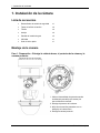
Mounting the Camera
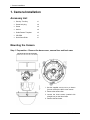
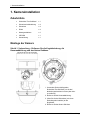
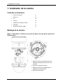
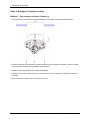
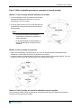
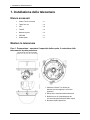
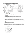
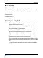
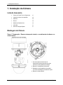
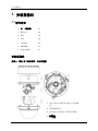
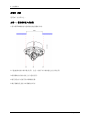
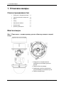
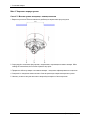
Step 1. Preparation – Remove the dome cover, camera liner and back case
1. Use the supplied
security torx key to loosen
(but not remove) the three cover screws.
2. Remove the camera liner.
3. Loosen the three screws (marked with
triangle icon) on the dome base.
4. Remove the back case.
2 Quick Start Guide

1. Camera Installation
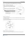
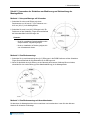
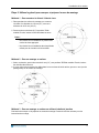
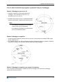
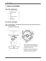
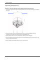
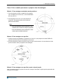
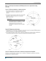
Step 2. Use the template to mark-out and prepare the mounting area
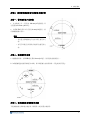
Method 1: To flush mount using screws
1. Create a circular opening in the mounting surface with
a diameter of 120 mm (4.7”) with tolerances of -0/+5 mm (-
0/.0.2”).
2. Create three 6 mm (0.2”) holes at the T3 template
positions. Then insert the screw anchors into the holes.
Notes:
- Not intended for drop ceiling installation without
appropriate lanyard.
- Not intended for installation in ceilings used for
environmental air return.
Method 2: To surface mount
1. According to your needs, create 6 mm (0.2”) holes at the T1/T2 template positions. Then insert the
screw anchors into the holes.
2. If you want to feed wiring from the hole on the top of the back case, create a circular opening (bottom
conduit hole) in the mounting surface.
Method 3: To surface mount using junction box
No need to mark-out and prepare the mounting areas. Skip to next section for mounting instructions.
3

1. Camera Installation
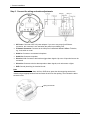
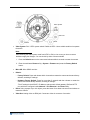
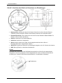
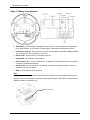
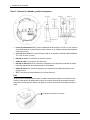
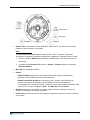
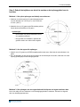
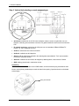
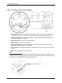
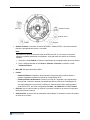
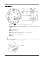
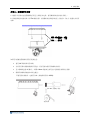
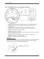
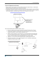
Step 3. Connect the wiring and make adjustments
AC Power: Connects to AC 24V power adapter. If you are to use power from Ethernet
connection, this connector is not used when the power is provided by PoE.
IP Network Connector: Connects to the LAN port of a standard 10Base/100Base-TX device,
e.g., hub, switch or router.
Audio In: Connects to an external microphone.
Audio Out: Connects to speaker.
Alarm In 1 & 2: Connects to devices that trigger alarm signals. Up to two 2 input devices can be
connected.
Alarm Out: Connects to device that responds to alarm signals, such as buzzers or lights.
GND: Ground (electricity) in electrical circuits
Note
To connect the Audio In/Out, Alarm In/Out or GND wires, press the relevant spring terminal tab
inward using an appropriate small tool and insert the wire into the opening. Then release the tab to
secure the wire.
Spring terminal tab
4 Quick Start Guide

1. Camera Installation
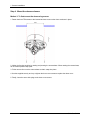
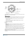
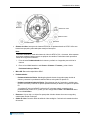
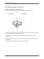
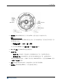
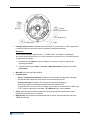
Video System
Micro SD
Video Out
Reset
Default
Video System: PAL / NT
SC system switch. Default is NTSC. Use a suitable small tool to operate
the switch.
Note:
After switching the video system mode from NTSC to PAL or vice versa, you have to restore
defaults to apply the changes. You can do this by either of these methods:
1. Press the Default button on the camera and release within 4 seconds to restart the camera.
2. Enter the web-based illustra utility > System > Firmware and press the Factory Default
button.
Micro SD: Micro SDHC card slot.
Default:
- Factory Default: Press and release within 4 seconds to restart the camera and restore factory
defaults, excluding IP settings*.
- Hardware Factory Default: Press for more than 5 seconds and then release to restart the
camera and restore factory defaults, including IP settings*.
*The IP settings include DHCP, IP address, subnet mask, default gateway, DNS and HTTP
port, which are configured under Network > IP & Ethernet in the illustra utility .
Reset: Using a paper clip or thin object, press the button for at least one second and release to
restart the camera.
Video Out: Analog video out RCA jack. Connects to video in connector of a monitor.
5

1. Camera Installation
Step 4. Mount the dome enclosure
Method 1: To flush mount the dome using screws
1. Fasten the three TP4 screws to the inserted anchors to secure the dome enclosure in place.
2. Adjust the focusing position by rotating and panning the camera base. When rotating the camera base,
do not rotate it past the stop point.
3. Fit the camera liner over the camera base so that it snaps into place.
4. Use the supplied security torx key to tighten the three cover screws to replace the dome cover.
5. Finally, insert the screw hole plugs to the three cover screws.
6 Quick Start Guide

1. Camera Installation
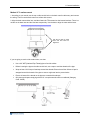
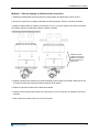
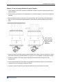
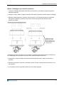
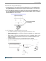
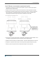
Method 2: To surface mount
1. According to your needs, use the top or side conduit hole on the back case for cable entry and connect
the wiring. Then mount the back case on a surface with screws.
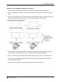
2. Align the back case and the lens, and then fasten the TP4 screws into the inserted anchors. There is a
red dot on the base case and the lens base respectively. Use the dots to align the case and the base.
Use the red dots on back
case and lens base fo
r
alignment.
If you are going to use the side
conduit hole, note that:
Use a 3/4" NPT (National Pipe Thread) pipe to feed the cables.
Before inserting the pipe to the side conduit hole, use a tape to seal the threads of the pipe.
Wrap at least 12 full loops of seal tape around the threads. Ensure that all the 100mm of tape is
wrapped around the threads of the pipe to ensure a tight seal and to prevent leaks.
Ensure all areas of the thread on the pipe are covered with seal tape.
Only those seal tapes complying with the UL’s requirements should be considered (Category
Code: JNGR).
7

1. Camera Installation
3. Adjust the focusing position by rotating and panning the camera base. Note that the back case side
conduit hole is the point where the camera will not rotate past.
4. Fit the camera liner over the camera base so that it snaps into place.
5. Use the supplied security torx key to tighten the three cover screws to replace the dome cover.
6. Finally, insert the screw hole plugs to the three cover screws.
8 Quick Start Guide

1. Camera Installation
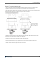
Method 3: To mount using junction box
1. Tie your wiring into a junction box and feed the leads through the top knock-out on the back case.
2. Tighten the screws to secure the back case to the junction box. Then connect the wiring.
3. Align the back case and the lens, then fasten the three screws. There is a red dot on the base case
and the lens base respectively. Use the dots to align the case and the base.
Use the red dots on
back case and lens
base for alignment.
4. Adjust the focusin
g position by rotating and panning the camera base. Note that the back case side
conduit hole is the point where the camera will not rotate past.
5. Fit the camera liner over the camera base so that it snaps into place.
6. Use the supplied security torx key to tighten the three cover screws to replace the dome cover.
7. Finally, insert the screw hole plugs to the three cover screws.
9

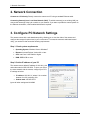
2. Network Connection
2. Network Connection
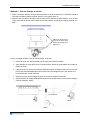
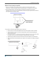
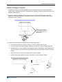
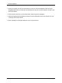
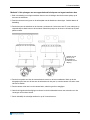
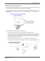
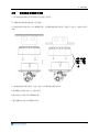
Connect to a PC directly: Directly connect the camera to a PC using a standard Ethernet cable.
Connecting Camera(s) to a Local Area Network (LAN): To add the camera(s) to an existing LAN, just
connect the camera(s) to the hub or switch on your network. If you want to provide the camera power via
the Ethernet connection, a PoE-enabled hub/switch is required.
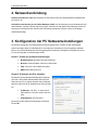
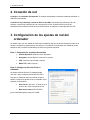
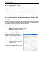
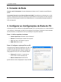
3. Configure PC Network Settings
The camera comes with a web-based setup utility, allowing you to view the video of the camera and
configure the camera for optimal use in your environment. To access the camera’s web-based control
utility, you need a PC that meets the following requirements:
Step 1: Check system requirements
Operating System: Windows Vista or Windows 7
Browser: Internet Explorer Version 8.0 or later
CPU: Intel Core 2 duo P8400 or higher
RAM: DDR3 4GB or more
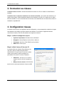
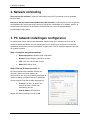
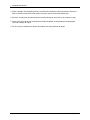
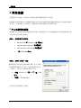
Step 2: Set the IP address of your PC
The camera uses a default IP address of 192.168.1.168
and subnet mask of 255.255.255.0. To have your PC on
the same network with the camera, configure your PC’s
IP settings as below:
IP address: 192.168.1.X, where X is a number
between 2 to 254, excluding 168.
Subnet mask: 255.255.255.0.
Ignore all other settings and click OK.
10 Quick Start Guide

3. Configure PC Network Settings
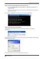
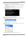
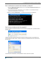
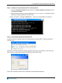
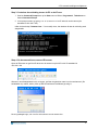
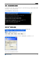
Step 3: Verify the connection between the PC and the IP Cam
1. Launch the Command Prompt by clicking the Start menu, Programs, Accessories and then
Command Prompt.
2. At the prompt window, type ping x.x.x.x, where x.x.x.x is the IP address of the camera (the
default is 192.168.1.168).
If the message of “Reply from…” appears, it means the connection is established.
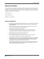
Step 4: Access the camera from IE browser
Open the IE browser and enter the IP address of the camera in the URL field. The default is
192.168.1.168.
When prompted to login, enter the user name and the password. (The defaults: admin, admin). Note that
the password is case-sensitive.
Upon successful login, you will see the live view screen of your camera.
11

illustra 600/610 Außenbereich HD Mini-Kugelkamera
Kurzanleitung
Version: 20110902
8200-2755-0600 A0

Urheberrecht
1
Urheberrecht
Gemäß Urheberrechtsgesetzen dürfen die Inhalte dieser Anleitung ohne vorheriges schriftliches
Einverständnis von Tyco International Ltd. weder vollständig noch in Auszügen kopiert, fotokopiert,
reproduziert, übersetzt oder auf eine elektronische oder maschinenlesbare Form reduziert werden. ©
2010 und zugehörige Unternehmen. Alle Rechte vorbehalten.
American Dynamics
6600 Congress Avenue
Boca Raton, FL 33487 U.S.A.
Hinweise zur Benutzung
• Diese Anleitung ist für Administratoren und Benutzer der Netzwerkkamera gedacht. Bitte
lesen Sie sie vor der Benutzung der Kamera sorgfältig durch. Vor der Nutzung der Kamera
sollten sämtliche Anforderungen erfüllt werden.
• Wir übernehmen keine Haftung für technische oder typografische Fehler und behalten uns
das Recht vor, Produkte und die Anleitungen ohne weitere Benachrichtigung zu ändern.
• Bewahren Sie dieses Dokument für zukünftige Zwecke auf.
• Die Kamera ist für Stromquellen von entweder 24V AC (Wechselstrom) oder PoE (Strom
über Ethernet) mit Einhaltung der LPS Richtlinien geeignet. Schließen Sie nur die Kamera
an dieses erforderliche Stromsystem an.
• Die Kamera muss auf einer stabilen Montagefläche installiert werden.
• Halten Sie die Kamera und anderes Zubehör trocken.
• Wir übernehmen keine Haftung für Schäden, die durch unsachgemäße Benutzung
entstehen.
• Die gesamte Installation sollte durch Fachpersonal erfolgen.
• Für Anwendung im Freien mit einer Stromversorgung: Wenn die Stromversorgung im Freien
installiert wird, muss sie als regenfeste/regendichte Klasse 2/LPS Stromversorgung oder
Klasse 2/LPS Stromversorgung, welche UL 60950-1 Abschnitt 1 und Abschnitt 22 entspricht,
gelistet sein.
• Verkabelungsmethode für die Stromquelle: Die Verkabelungsmethode sollte den Artikeln
725 und 300 des National Electrical Code für Klasse 2 Stromkreise und Verkabelung in
Kabelschächten entsprechen.

1. Kamerainstallation
2 Kurzanleitung
1. Kamerainstallation
Zubehörliste
• Sicherheits-Torx-Schlüssel x 1
• Schraubenlochabdeckung x 4
• Schrauben x 4
• Dübel x 4
• Montageschablone x 2
• CD-ROM x 1
• Kurzanleitung x 1
Montage der Kamera
Schritt 1. Vorbereitung – Entfernen Sie die Kugelabdeckung, die
Kameraabdichtung und das hintere Gehäuse.
1. Verwenden Sie den beiliegenden
Sicherheits-Torx-Schlüssel, um die drei
A
bdeckungsschrauben zu lösen (aber nicht
zu entfernen).
2. Entfernen Sie die Kameraabdichtung.
3. Lösen Sie die drei Schrauben (mit einem
Dreieckssymbol markiert) an der
Kugelbasis.
4. Entfernen Sie das hintere Gehäuse.

1. Kamerainstallation
3
Schritt 2. Verwenden der Schablone zur Markierung und Vorbereitung der
Montagefläche
Methode 1: Unterputz-Montage mit Schrauben
1. Schneiden Sie eine runde Öffnung mit einem
Durchmesser von 120 mm (4,7") mit Toleranzen von -
0/+5 mm (-0/0,2") in die Montagefläche.
2. Schneiden Sie zwei 6 mm (0,2") Öffnungen in die T3
Positionen auf der Schablone. Fügen Sie anschließend
die Schraubendübel in die Öffnungen ein.
Hinweise:
- Nicht für umgekehrte Deckeninstallation ohne
entsprechendes Trageband geeignet.
- Nicht zur Installation an Decken geeignet, die
zum Luftaustausch dienen.
Methode 2: Oberflächenmontage
1. Schneiden Sie je nach Anwendung 6mm (0,2") Öffnungen in die T1/T2 Positionen auf der Schablone.
Fügen Sie anschließend die Schraubendübel in die Öffnungen ein.
2. Wenn Sie die Kabel durch die Öffnung an der Oberseite des hinteren Gehäuses führen möchten,
schneiden Sie eine runde Öffnung (untere Kabelkanalöffnung) in die Montagefläche.
Methode 3: Oberflächenmontage mit Anschlusskasten
Sie brauchen die Montagebereiche nicht zu markieren und vorzubereiten. Lesen Sie den nächsten
Abschnitt für Hinweise zur Montage.

1. Kamerainstallation
4 Kurzanleitung
Schritt 3. Anschluss der Kabel und Vornehmen von Einstellungen
• Netzanschluss: Anschluss an das AC 24V Netzteil. Wenn Sie den Strom über die Ethernet-
Verbindung (PoE) verwenden möchten, braucht dieser Anschluss nicht verwendet werden.
• IP Netzwerkanschluss: Zum Anschluss an den LAN Port eines Standard 10Base/100Base-TX
Gerätes, z.B. Hub, Switch oder Router.
• Audio In: Anschluss an ein externes Mikrofon.
• Audio Out: Anschluss an Lautsprecher.
• Alarm In 1 & 2: Anschluss an Geräte, die Alarmsignale auslösen können. Bis zu 2
Eingangsgeräte können angeschlossen werden.
• Alarm Out: Anschluss an Geräte, die auf Alarmsignale reagieren, wie z.B. Summer oder Lampen.
• GND: Erdung (Elektrik) in elektrischen Schaltkreisen.
Hinweis
Um Audio In/Out, Alarm In/Out oder GND-Kabel anzuschließen, drücken Sie die entsprechende
Federklemme mit einem geeigneten, kleinen Gegenstand nach unten und führen Sie das Kabel in
die Öffnung ein. Lassen Sie die Klemme anschließend los, um das Kabel zu befestigen.
Federklemme

1. Kamerainstallation
5
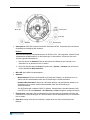
• Videosystem: NTSC/PAL System Umschalter. Standard ist NTSC. Verwenden Sie einen kleinen
Gegenstand zur Betätigung des Schalters.
Hinweis:
Nach dem Wechsel des Videosystemmodus von NTSC zu PAL, oder umgekehrt, müssen Sie die
Standardwerte wiederherstellen, um die Änderungen zu übernehmen. Sie können dies durch
eine der folgenden Methoden tun:
1. Drücken Sie auf die Standard Taste an der Kamera und lassen Sie sie innerhalb von 4
Sekunden los, um die Kamera neu zu starten.
2. Rufen Sie das Web-basierte illustra Programm auf > System > Firmware und drücken Sie
auf die Schaltfläche Werksstandard.
• Micro SD: Micro-SDHC Kartensteckplatz.
• Standard:
- Werksstandard: Drücken und innerhalb von 4 Sekunden loslassen, um die Kamera neu zu
starten und den Werksstandard außer den IP-Einstellungen* wiederherzustellen.
- Hardware Werksstandard: Länger als 5 Sekunden drücken und anschließend loslassen, um
die Kamera neu zu starten und den Werksstandard außer den IP-Einstellungen*
wiederherzustellen.
*Die IP-Einstellungen umfassen DHCP, IP-Adresse, Subnetzmaske, Standard Gateway, DNS
und HTTP Port, die unter Netzwerk > IP & Ethernet im illustra Programm konfiguriert werden.
• Zurücksetzen: Verwenden Sie eine Büroklammer oder einen dünnen Gegenstand, drücken Sie
mindestens eine Sekunde lang auf die Taste und lassen Sie sie anschließend los, um die Kamera
neu zu starten.
• Video Out: Analog Video Out Cinch-Buchse. Anschluss an den Video In Anschluss eines
Monitors.
Videosystem
Video Out
Standard
Zurücksetzen
Micro SD

1. Kamerainstallation
6 Kurzanleitung
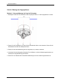
Schritt 4. Montage des Kugelgehäuses
Methode 1: Unterputz-Montage der Kugel mit Schrauben
1. Befestigen Sie die drei TP4 Schrauben an den eingefügten Dübeln, um das Kugelgehäuse zu sichern.
2. Passen Sie die Fokusposition an, indem Sie die Kamerabasis drehen und schwenken. Drehen Sie die
Kamerabasis nicht über den Haltepunkt hinaus.
3. Passen Sie die Kameraabdichtung über der Kugelbasis an, so dass sie einrastet.
4. Verwenden Sie den beiliegenden Sicherheits-Torx-Schlüssel, um die drei Abdeckungsschrauben zum
Austausch der Kugelabdeckung festzuziehen.
5. Setzen Sie zum Abschluss die Schraubenlochabdeckungen an den 3 Abdeckungsschrauben ein.

1. Kamerainstallation
7
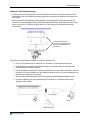
Methode 2: Oberflächenmontage
1. Verwenden Sie je nach Bedarf den oberen oder seitlichen Auswerfer am hinteren Gehäuse für den
Kabeleingang und dem Anschluss der Kabel. Montieren Sie das hintere Gehäuse mit Schrauben auf
eine Fläche.
2. Richten Sie das hintere Gehäuse und das Objektiv aus und befestigen Sie anschließend die TP4
Schrauben in den eingefügten Dübeln. Auf dem Basisgehäuse und der Objektivbasis befindet jeweils
sich ein roter Punkt. Verwenden Sie diese Punkte, um das Gehäuse und die Basis aneinander
auszurichten.
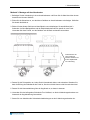
Wenn Sie die seitliche Kabelkanalöffnung verwenden, beachten Sie:
• Ein 3/4" NPT (National Pipe Thread) Rohr zu verwenden, um die Kabel durchzuführen.
• Dichtungsband zum Abdichten des Rohrgewindes zu verwenden, bevor Sie das Rohr in die
seitliche Kabelkanalöffnung einführen.
• Das Dichtungsband mindestens 12 Mal um das Gewinde zu wickeln. Stellen Sie sicher, dass die
gesamtem 100 mm des Bandes um das Gewinde gewickelt sind, um eine sichere Abdichtung zu
gewährleisten und Lecks zu vermeiden.
• Sicherzustellen, dass alle Bereiche des Rohrgewindes mit Dichtungsband abgedeckt sind.
• Nur Dichtungsbänder, die den UL-Bestimmungen entsprechen, verwendet werden sollten
(Kategorie Code: JNGR).
Verwenden Sie die roten
Punkte am hinteren Gehäuse
und an der Objektivbasis zur
A
usrichtung.
3/4" NPT Pipe
Kabel
A
bdichtungsmittel
A página está carregando...
A página está carregando...
A página está carregando...
A página está carregando...
A página está carregando...
A página está carregando...
A página está carregando...
A página está carregando...
A página está carregando...
A página está carregando...
A página está carregando...
A página está carregando...
A página está carregando...
A página está carregando...
A página está carregando...
A página está carregando...
A página está carregando...
A página está carregando...
A página está carregando...
A página está carregando...
A página está carregando...
A página está carregando...
A página está carregando...
A página está carregando...
A página está carregando...
A página está carregando...
A página está carregando...
A página está carregando...
A página está carregando...
A página está carregando...
A página está carregando...
A página está carregando...
A página está carregando...
A página está carregando...
A página está carregando...
A página está carregando...
A página está carregando...
A página está carregando...
A página está carregando...
A página está carregando...
A página está carregando...
A página está carregando...
A página está carregando...
A página está carregando...
A página está carregando...
A página está carregando...
A página está carregando...
A página está carregando...
A página está carregando...
A página está carregando...
A página está carregando...
A página está carregando...
A página está carregando...
A página está carregando...
A página está carregando...
A página está carregando...
A página está carregando...
A página está carregando...
A página está carregando...
A página está carregando...
A página está carregando...
A página está carregando...
A página está carregando...
A página está carregando...
A página está carregando...
A página está carregando...
A página está carregando...
A página está carregando...
A página está carregando...
A página está carregando...
A página está carregando...
A página está carregando...
A página está carregando...
A página está carregando...
A página está carregando...
A página está carregando...
A página está carregando...
A página está carregando...
A página está carregando...
A página está carregando...
A página está carregando...
A página está carregando...
A página está carregando...
A página está carregando...
A página está carregando...
A página está carregando...
A página está carregando...
A página está carregando...
A página está carregando...
-
 1
1
-
 2
2
-
 3
3
-
 4
4
-
 5
5
-
 6
6
-
 7
7
-
 8
8
-
 9
9
-
 10
10
-
 11
11
-
 12
12
-
 13
13
-
 14
14
-
 15
15
-
 16
16
-
 17
17
-
 18
18
-
 19
19
-
 20
20
-
 21
21
-
 22
22
-
 23
23
-
 24
24
-
 25
25
-
 26
26
-
 27
27
-
 28
28
-
 29
29
-
 30
30
-
 31
31
-
 32
32
-
 33
33
-
 34
34
-
 35
35
-
 36
36
-
 37
37
-
 38
38
-
 39
39
-
 40
40
-
 41
41
-
 42
42
-
 43
43
-
 44
44
-
 45
45
-
 46
46
-
 47
47
-
 48
48
-
 49
49
-
 50
50
-
 51
51
-
 52
52
-
 53
53
-
 54
54
-
 55
55
-
 56
56
-
 57
57
-
 58
58
-
 59
59
-
 60
60
-
 61
61
-
 62
62
-
 63
63
-
 64
64
-
 65
65
-
 66
66
-
 67
67
-
 68
68
-
 69
69
-
 70
70
-
 71
71
-
 72
72
-
 73
73
-
 74
74
-
 75
75
-
 76
76
-
 77
77
-
 78
78
-
 79
79
-
 80
80
-
 81
81
-
 82
82
-
 83
83
-
 84
84
-
 85
85
-
 86
86
-
 87
87
-
 88
88
-
 89
89
-
 90
90
-
 91
91
-
 92
92
-
 93
93
-
 94
94
-
 95
95
-
 96
96
-
 97
97
-
 98
98
-
 99
99
-
 100
100
-
 101
101
-
 102
102
-
 103
103
-
 104
104
-
 105
105
-
 106
106
-
 107
107
-
 108
108
-
 109
109


American Dynamics illustra 600 Guia rápido
- Tipo
- Guia rápido
- Este manual também é adequado para
em outras línguas
- español: American Dynamics illustra 600 Guía de inicio rápido
- français: American Dynamics illustra 600 Guide de démarrage rapide
- italiano: American Dynamics illustra 600 Guida Rapida
- English: American Dynamics illustra 600 Quick start guide
- русский: American Dynamics illustra 600 Инструкция по началу работы
- Nederlands: American Dynamics illustra 600 Snelstartgids
- Deutsch: American Dynamics illustra 600 Schnellstartanleitung
Artigos relacionados

Outros documentos
-
 Heatsail Dome Bow Bracket Manual do usuário
-
Tyco American Dynamics Illustra 625 Quick Reference Manual
-
-
Avigilon 1.0-H3-D2 Guia de instalação
-
-
Avigilon H3-DP2 Guia de instalação
-
-
Avigilon H3-BO1-IR Guia de instalação
-
Grandstream GXV3611IR_HD Quick Installation Guide
-
Vivotek IB836BA-HF3 Manual do usuário
