Whirlpool AKR 631 IX WP Manual do proprietário
- Categoria
- Exaustores
- Tipo
- Manual do proprietário

5019 318
33157
AKR 631-666-812-966
AKR 943-948-952-995-996
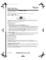
INSTALLATIONSBESCHREIBUNG
Mindestabstand über der Kochfläche: 50 cm (Elektrokochplatten), 70 cm (Gas-, Öl-
oder Kohlekochplatten). Schreiben die Installationsanweisungen des Gaskochfelds
einen größeren Abstand vor, ist dieser natürlich zu beachten. Folgen Sie bei der
Installation der Nummerierung (1
Ö
2
Ö
3
Ö
.....). Schließen Sie das Gerät erst nach
seiner kompletten Installation an das Stromnetz an. Achtung! Das Auslassrohr und die
Befestigungsmanschetten sind nicht im Lieferumfang inbegriffen und müssen
gesondert erworben werden.
INSTALLATION DATA SHEET
Minimum height above cooker: 50 cm (electric cookers), 65 cm (gas, gas oil or coal
cookers). If the installation instructions for a gas cooker specify a greater distance,
then this distance must be observed. To install, follow steps (1
Ö
2
Ö
3
Ö
.....). Do not
connect the hood to the electrical power supply until installation is completed.
Warning! The exhaust pipe and clamps are not supplied and must be bought
separately.
FICHE D'INSTALLATION
Distance minimale par rapport à la cuisinière : 50 cm (cuisinière électrique), 70 cm
(cuisinière à gaz, mazout ou charbon). Si les instructions d'installation du dispositif de
cuisson à gaz indiquent une distance supérieure, il est nécessaire de la respecter. Pour
le montage, suivez la numérotation (1
Ö
2
Ö
3
Ö
.....). Ne branchez pas l'appareil tant
que l'installation n'est pas terminée. Attention ! Le conduit d'évacuation et les colliers
de fixation ne sont pas fournis et doivent être achetés à part.
INSTALLATIEKAART
Minimumafstand tot het kooktoestel: 50 cm (elektrische kooktoestellen), 70 cm
(kooktoestellen op gas, olie of kolen). Als de installatie-instructies van het kooktoestel
op gas een grotere afstand aangeven, moet hiermee rekening gehouden worden. Volg
voor de montage de nummering (1
Ö
2
Ö
3
Ö
.....). Geef het apparaat geen stroom totdat
de installatie geheel voltooid is. Let op! De afvoerbuis en de klembanden worden niet
bijgeleverd en moeten apart worden aangeschaft.
D
GB
F
NL
31833157.fm Page 1 Friday, April 1, 2005 5:04 PM

5019 318
33157
AKR 631-666-812-966
AKR 943-948-952-995-996
FICHA DE INSTALACIÓN
Distancia mínima desde los quemadores: 50 cm (fuegos eléctricos), 70 cm (fuegos de
gas, gasóleo o carbón). Si en las instrucciones de instalación de la placa de cocina a gas
se especifica una distancia mayor respecto a la indicada, es necesario tenerlo en
cuenta. Para el montaje, siga la numeración (1
Ö
2
Ö
3
Ö
...). No conecte el aparato a la
corriente eléctrica hasta que la instalación esté completamente finalizada. ¡Atención!
El tubo de descarga y las abrazaderas de fijación no están incluidas y se compran
aparte.
FICHA DE INSTALAÇÃO
Distância mínima dos fogões: 50 cm (fogões eléctricos), 70 cm (fogões a gás, óleo ou
carbono. Respeite as instruções de instalação do dispositivo de cozedura a gás se estas
especificarem uma distância superior à indicada. Para montar siga a numeração
(1
Ö
2
Ö
3
Ö
.....). Não ligue o aparelho à corrente eléctrica enquanto a instalação não
estiver concluída. Atenção! O tubo de descarga e as braçadeiras de fixação não são
fornecidas e devem ser compradas à parte.
SCHEDA INSTALLAZIONE
Distanza minima dai fuochi: 50 cm (fuochi elettrici), 70 cm (fuochi a gas, gasolio o
carbone). Se le istruzioni di installazione del dispositivo di cottura a gas specificano una
distanza maggiore rispetto a quella specificata, bisogna tenerne conto. Per il
montaggio seguire la numerazione (1
Ö
2
Ö
3
Ö
.....). Non dare corrente all’apparecchio
finché l’installazione non è totalmente completata. Attenzione! Il tubo di scarico e le
fascette di fissaggio non sono fornite e vanno acquistate a parte.
ùüùü+ùùùþ
ü$12.)12.1.)2"0120"FP02!"0120"FP0120".0! #
02!0. #0! # ü /0"0.212.1"2"012.".0! #1#12 *
0.*20!.)12.1101$1000 #$0 !12003.!)1202"1$02"
/0"+.22 21. #1202.!1
Ö
Ö
Ö
2! 3 / 2020
002!)!0*.21#10#!2 !&12"0.212.1"! 1 $
1&."..&".2. !.120!&1"/0/.202..!0.. 2 *
$&!12
E
P
I
GR
31833157.fm Page 2 Friday, April 1, 2005 5:04 PM

5019 318
33157
AKR 631-666-812-966
AKR 943-948-952-995-996
a
a
a
31833157.fm Page 3 Friday, April 1, 2005 5:04 PM

5019 318
33157
AKR 631-666-812-966
AKR 943-948-952-995-996
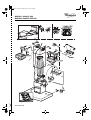
Remove the perimeter extraction panel (if relevant) and the grease filter/s.
Pre-assemble the steam deflector on the motor assembly (if relevant): (a.) fit the steam deflector to the rails of the motor
assembly (remove the two travel stop screws from the steam deflector if necessary), (b.) connect up the control panel and
the lamps, (c.) fix in place with the 14 screws (max).
1. Mark a line on the wall right up to the ceiling, corresponding to the centre-line of the hood.
2. Apply the drilling template to the wall: Align the vertical centre-line on the drilling template with the centre-line drawn
on the wall. The template's bottom edge represents the bottom edge of the hood.
3. Place the mounting bracket over the drilling template so that it matches the outlined rectangle. Mark and drill the two
outside holes. Remove the drilling template. Insert two wall plugs in the holes and fix the hood mounting bracket in place
with two 5 x 45 mm screws.
4. Hang the hood on the mounting bracket. Adjust gap (5.) and the horizontal alignment (6.) of the hood.
5. Remove the hood from the bracket. Drill the holes (9. - Ø 8 mm - see step 7.). Insert two wall plugs (10.).
6. Apply the flue mounting bracket G to the wall against the ceiling. (Align the small slot in the bracket with the centre-line
drawn on the wall. See step 1. Fix the bracket in place with two wall plugs (Ø 8 mm) and 2 screws 12).
7. Hang the hood on the bottom mounting bracket. (14.) Fix the hood to the wall with two 5 x 45 mm screws
(ABSOLUTELY NECESSARY). Plug the two holes if they are visible from the outside.
8. Connect an exhaust pipe to the to the collar B, the fumes must be ducted to the outside (extractor version) or towards
the deflector (filter version). Fix the deflector F to the flue support bracket G with 4 screws (2 screws only for 120 cm
wide model). If the collar (bayonet coupling) is not already fitted, insert it on the deflector F and secure it with 1 screw.
9. Make all necessary electrical connections.
10. Apply the flues and fix them with 2 screws (17a) to the flue support G (17b).
11. Slide the bottom section of the flue all the way over the extraction unit until it engages the seat above the hood.
12. (120 cm wide model only) fix the bottom section of the flue to the hood with 2 screws.
Re-fit the grease filter/s and, if a perimeter extraction panel is fitted, check for correct operation.
Important! Only for model AKR 996: proceed with hob selection and manual calibration of the sensors. For this purpose,
read the paragraph on the next page “Important - upon initial installation”.
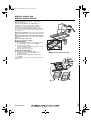
6
1. Control panel.
2. Grease filter.
3. Halogen bulbs.
4. Steam deflector.
5. Telescopic flue.
6. Perimeter extraction
panel (if fitted) and
release handle (f3).
7. Sensors (only present on
some models).
INSTALLATION - ASSEMBLY INSTRUCTIONS
IF NL E PGBD GR
31833157.fm Page 8 Friday, April 1, 2005 5:04 PM

5019 318
33157
AKR 631-666-812-966
AKR 943-948-952-995-996
Analogue control panel
Light : move the switch to the right or press the button to switch on.
Extraction speed : Move the switch to the right or press the next button to increase extraction speed
(or open the electric shutter ).
Digital control panel with sensors
The hood is fitted with a series of sensors which enable it to operate in 2 modes:
Automatic
mode
and
Manual mode
.
Automatic mode:
the hood switches on automatically, depending on the ambient temperature (and heat) and variations in
this detected by the hood's sensors. See description of Button 3 function.
Manual mode:
the hood is switched on by the user.
Description of Buttons
1. OFF/Stand by button:
When the hood is OFF, all the controls are disabled (all LEDs are off).
When on stand-by, the hood is ready to operate in “
Manual mode
”, LED C lights up.
2. Light ON/OFF button: always works, even when the hood is OFF.
3. ON/OFF button “
Automatic mode
”: press to activate this mode (LED C and E on) the hood switches on automatically,
selecting a suitable extraction speed in accordance with the ambient temperature (and heat) and any variations in this
detected by the hood's sensors. Press again to revert to
“Manual mode”
: LED E switches off, LED C remains on (stand
by). The hood will continue to run for a few minutes after you have finished cooking but can be turned off by pressing
buttons 1 or 3. The automatic function (LED on) stops a few minutes after the motor has been switched off. The
automatic function must be switched on every time you start cooking.
4. ON/OFF button for controlling intensive extraction speed in “
Manual mode
” (LED D switches on): when selected, it
operates for 5 minutes, after which time the hood automatically reverts to the previously selected extraction speed.
5. Buttons for controlling extraction speed 1 - 2 - 3 in “
Manual mode
”.
Description of LEDs
A.
Carbon filter
saturation led indicator
: this led lights up to indicate that the carbon filter needs to be cleaned or replaced.
Important: this indicator must be activated in order for the hood to work:
to activate it, press buttons 4 and 5 at the
same time - LED B lights up first, followed by LED A to indicate that the led indicator is working.
B.
Grease filter saturation led indicator: this led lights up to indicate that the grease filter needs to be cleaned.
C.
“Stand by” led indicator.
D.
Intensive speed led indicator.
E.
“Automatic mode” led indicator.
F.
Extraction speed 1 led indicator.
G.
Extraction speed 2 led indicator.
H.
Extraction speed 3 led indicator.
Reset filters indicator:
After cleaning or replacing the filters, with the hood on
Stand by
press Button 1 for more than 3 seconds.
Safety function: this function is activated ONLY with the hood on stand-by, in the event of any SUDDEN, VIOLENT
increase in the temperature detected by the sensors, upon which the hood switches to “
Automatic mode
” and, if necessary,
selects a suitable extraction speed.
Important - upon initial installation:
Selecting the hob type: to ensure accurate “reading” by the sensors, the latter must be calibrated to suit the type of hob
as follows: with the hood OFF, press buttons 3 and 4 at the same time until either LED F for gas hobs, LED G for induction
hobs or LED H for electric hobs lights up.
Automatic and manual sensor calibration: the hood automatically “calibrates” sensor operation, but under certain
circumstances (e.g.: in the event of a prolonged power failure or upon initial installation) calibration can be carried out
manually, with the hood OFF, by pressing buttons 5 and 6 at the same time for more than 3 seconds, otherwise you can wait
until the hood carries out calibration automatically.
PRODUCT SHEET
IF NL E PGBD GR
31833157.fm Page 9 Friday, April 1, 2005 5:04 PM

5019 318
33157
AKR 631-666-812-966
AKR 943-948-952-995-996
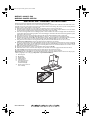
Maintenance
ALWAYS disconnect the hood from the mains before
performing maintenance.
Wash the grease filter and the carbon filter in a
dishwasher once a month, at the highest possible
temperature, using normal dishwasher detergent. It is
recommended to wash the filters on the their own.
After washing, reactivate the carbon filter by drying it in
the oven at 100 °C for 10 minutes. Fit a new carbon filter
every 3 years.
Remove the grease filters - Fig. 1: push the spring release
handle backwards (f1) then remove the filter downwards
(f2).
Clean the perimeter extraction panel (if provided) as
often as the grease filter, using a cloth and a mild liquid
detergent.
Never use abrasive substances.
Clean the sensor plate regularly.
Replacing bulbs
1. Use a small screwdriver or any other suitable tool to
prise off (m-Fig. 1) the lamp cover (p-Fig.1).
2. Remove the burnt-out bulb.
Use max 20 W halogen bulbs only, taking care not to
touch them with your hands.
3. Close the lighting unit (snap-on).
Fitting the carbon filter:
1. Remove the grease filter (f1/f2 - Fig. 1).
2. Remove the filter holder by turning the knobs
(g - Fig. 2) through.
3. Fit the carbon filter (i - Fig. 2) in the filter holder
(h - Fig.2).
Reverse the above procedure to re-fit the filter holder and
grease filter.
Fig. 2
f3
* Only present on some models
Fig. 1
IF NL E PGBD GR
31833157.fm Page 10 Friday, April 1, 2005 5:04 PM
-
 1
1
-
 2
2
-
 3
3
-
 4
4
-
 5
5
-
 6
6


Whirlpool AKR 631 IX WP Manual do proprietário
- Categoria
- Exaustores
- Tipo
- Manual do proprietário
em outras línguas
Artigos relacionados
-
Whirlpool AKR 943 IX Program Chart
-
-
Whirlpool AKR 996 IX Program Chart
-
Whirlpool AKR 909 IX Program Chart
-
Whirlpool AKR 904-1 IN Program Chart
-
Whirlpool AKR 901 IX Program Chart
-
Whirlpool AKR 927 IX Program Chart
-
-
Whirlpool AKR 700 AL Manual do proprietário
-
Whirlpool AKR 976/01 IX Manual do proprietário