
51985323
Edition 5
May 2014
Save These Instructions
Product Information
Air Percussive Drill
JH40 Series
EN
Product Information
Especicaciones del producto
Spécications du produit
产品信息
Especicações do Produto
ES
FR
PT
ZH

2 51985323_ed5
4
9
5
3
2
1
6
8
8h
7
(Dwg. 16572133)
1
2
3
5
6
7
8
9
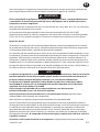
IR # IR # inch (mm) NPT IR # IR # IR #
--- 16LUB16 3/4 (19) 3/4 --- Rock Drill Oil ---

51985323_ed5 EN-1
EN
Product Safety Information
Intended Use:
The Series JH40 Jackhamer is capable of drilling 2 inch (51 mm) diameter holes up to
18 feet (5.5 m) deep in medium to hard rock. It is particularly suitable for construction work,
medium industrial maintenance work and for general utility work in quarries and mines.
For additional information refer to Product Safety Information Manual Form 04584975.
Manuals can be downloaded from ingersollrandproducts.com
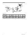
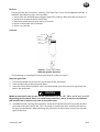
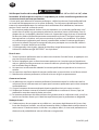
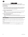
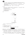
Installation and Lubrication
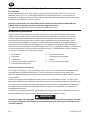
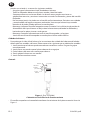
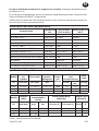
Size air supply line to ensure tool’s maximum operating pressure (PMAX) at tool inlet. Drain
condensate from valve(s) at low point(s) of piping, air lter and compressor tank daily. Install
a properly sized Safety Air Fuse upstream of hose and use an anti-whip device across any
hose coupling without internal shut-o, to prevent hose whipping if a hose fails or coupling
disconnects. See drawing 16572133 and table on page 2. Maintenance frequency is shown in
circular arrow and dened as h=hours, d=days, and m=months. Items identied as:
1. Air lter 6. Thread size
2. Regulator 7. Anti-whip device
3. Lubricator 8. Oil
4. Emergency shut-o valve 9. Safety Air Fuse
5. Hose diameter
Air Supply Connections
Always use clean, dry air. Dust, corrosive fumes and/or excessive moisture can ruin an air tool. An
air line lter can greatly increase the life of an air tool. The lter removes dust and moisture.
Use quality hose designed for rock drill service. Rock drill hose is constructed with an outer
covering that resists abrasive wear and an oil resistant inner tube capable of withstanding the
heat of compressed air. Quality hose has a working pressure safety factor of at least 4 to 1 in
relation to burst.
When using new air hose, blow lubricated air through the hose for a duration of time that is long
enough to completely coat the inside with oil.
WARNING
Attach safety cables across hose couplings & ttings and install safety locking pins or clips
on coupling to prevent whipping air hoses.
Blow out the main air supply hose to get rid of moisture, rubber particles and dirt before
attaching the hose to the tool.
WARNING
Compressed air is dangerous. When blowing out an air hose, hold it rmly and point
it away from personnel and equipment. Never blow your clothes free of dust with
compressed air.

EN-2 51985323_ed5
EN
Before connecting the air hose to the air connection, pour 2 to 3 oz. (.06 to .09 L) of Rock Drill Oil
into the inlet. The tool is shipped from the factory with a standard 3/4” NPT male inlet thread.
Make sure all hoses and ttings are the correct size and are tightly secured. See diagram
Dwg. 16572133 on page 2 for a typical piping arrangement.
Air Requirements
An air compressor of sucient capacity is needed to provide the necessary volume of air at the
most ecient operating pressure to ensure eective and economical operation of the jackhamer.
The air requirements represent air pressure at the jackhamer inlet and not at the compressor.
There is always a certain amount of pressure drop between the compressor and the jackhamer;
only the pressure and volume at the tool is eective in doing work. If a hose is relatively short
and in good condition, the pressure drop between the compressor (or air receiver) and the
jackhamer should not exceed 15 percent of the initial pressure.
Low or inadequate air pressure at the jackhamer is costly and wasteful, and an insucient
volume if air will not allow it to operate eciently.
NOTICE
Proper lubrication is the most important single factor responsible for the service life of a
pneumatic jackhamer. A jackhamer can be seriously damaged during the rst few minutes
of operation if it is not properly lubricated.
Improper lubrication will prevent proper indexing of the rotation and ultimately reduce
the rotation speed. Prolonged usage of the jackhamer without proper lubrication will
cause damage to the unit. Always use an air line lubricator with these tools.
Install the Lubricator approximately 11.5 ft. (3.5 m) from the tool.
At the beginning of each eight hour shift and once during the shift, ll the air line lubricator
with the recommended oil.
Before lling any reservoir, clean the area around the ll plug.
Adjust the air line lubricator to provide a light lm of oil at the drill steel shank. Excessive
lubrication is indicated by blue smoke at the exhaust or oil running down the drill steel. Start
the adjustment by turning the lubricator needle valve clockwise until it is closed. Turn the valve
counterclockwise 3/4 of a turn for an initial starting point. Rotate the valve one way or the other
until the desired amount of lubrication is obtained. Always place the tool against the work
when checking lubrication.
When using a compressor mounted lubricator, hose length must not exceed 50 ft. (15 m).
When exhaust freezing occurs, add anti-freeze lubricant directly through the air inlet. Use
“KILFROST” lubricant or equivalent.
Store all oil in covered containers in an area that is relatively dust free to prevent contamination.

51985323_ed5 EN-3
EN
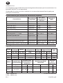
Rock Drill Oil Specications
Characteristic Test Procedure
90°F and Below
(32°C and Below)
Above 90°F
(Above 32°C)
Viscosity:
SUS at 100°F (38°C) ASTM-D2161 175 Min. 450 Min.
SUS at 210°F (99°C) ASTM-D2161 46 Min. 65 Min.
cST at 104°F (40°C) ASTM-D445 37 Min. 105 Min.
cST at 212°F (100°C) ASTM-D445 6 Min. 11 Min.
Pour Point, °F (°C) Max. ASTM-D97 -10°F (-23°C) -10°F (-23°C)
Flash Point, °F (°C) Max. ASTM-D92 370°F (188°C) 400°F (204°C)
Viscosity Index, Min. ASTM-D2270 90 90
Steam Emulsion No. Min. ASTM-1935-65 1200 1200
Consistency --- Stringy Stringy
Falex Load Test lbs. (kg) [Min.] ASTM-D2670 2000 lbs. (907 kg) 2000 lbs. (907 kg)
Timken E. P. Test lbs. (kg) [Min.] ASTM-D2782 30 lbs. (14 kg) 30 lbs. (14 kg)
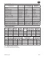
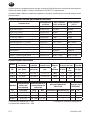
Product Specications
Model
Bore of
Cylinder
Working
Stroke
Chuck
Size Hex.
Blows
per
Minute
Air Consumption at
90 psi (6.2 bar)
Weight
(Net)
I.D. inch (mm) inch (mm) inch ft
3
/min. m
3
/min. lbs (kg)
JH40C1 2.5 (63.5) 2-5/8 (66.7) 7/8 x 3-1/4 2000 115 3.25 61 (27.7)
JH40C2 2.5 (63.5) 2-5/8 (66.7) 7/8 x 4-1/4 2000 115 3.25 61 (27.7)
JH40C3 2.5 (63.5) 2-5/8 (66.7) 1 x 4-1/4 2000 115 3.25 61 (27.7)
Model
Overall
Length
Recommended Air
Supply at the Inlet
Sound Level dB (A)
(ISO15744)
Vibration (m/s
2
)
(ISO28927)
I.D. inch (mm) psig bar † Pressure (L
p
) ‡ Power (L
w
) Level *K
JH40C1 22.5 (572) 90 - 100 6.2 - 6.9 -- -- -- --
JH40C2 22.5 (572) 90 - 100 6.2 - 6.9 -- -- -- --
JH40C3 22.5 (572) 90 - 100 6.2 - 6.9 -- -- -- --
† K
pA
= 3dB measurement uncertainty
‡ K
wA
= 3dB measurement uncertainty
* K = Vibration measurement uncertainty

EN-4 51985323_ed5
EN
WARNING
Sound and vibration values were measured in compliance with internationally recognized
test standards. The exposure to the user in a specic tool application may vary from these
results. Therefore, on site measurements should be used to determine the hazard level in
that specic application.
Operation
CAUTION
Do not operate the jackhamer when the drill bit is not against the work.
Never strike the tool with a blunt object; the housing may be broken or damaged.
Never attempt major maintenance of the tool on the job; take it to a repair shop.
Never drag the tool along the ground; the air ports in the exhaust may ll with dirt.
Always blow out the air supply hose before connecting it to the tool to remove any dirt
inside the hose.
Make sure the tool is well lubricated.
In extremely cold weather, keep drill steel tools wrapped in burlap or cloth until just
before you use them. At 0°F (-18°C) a hardened steel drill loses about 80% of its normal
shock resistance.
Always keep plastic caps or plugs in all ports when the tool is not in service.
Do not lift or transport the tool by the Throttle Lever. Damage can occur to the tool.
Operating Tips
Check the drill steel. The drill steel center hole should be open, and shanks should be at and
square - not chipped or rounded o. Be sure the shank of the drill steel is the proper length.
Be certain bits are properly ground. Dull bits are hard on the jackhamer and on the operator.
Drill Steel Care
It is very important that the threads of the drill steel be properly lubricated and cared for at
all times. Steels having stripped threads, cracks or severe galling must not be used. Also, care
should be taken while drilling not to bend the steel or gall threads due to misuse.
Bent steel produces unnecessary stresses and accelerates wear on front-head components.
Bent steel and severe thread galling can be avoided if the following steps are taken:
Be sure the steel is bottomed in the bit.
All the threads must be in good condition and well lubricated.
Always drill with a sharp bit. Dull bits cause excessive pounding and unnecessary stresses
on all threads and jackhamer parts.
Never approach the rock with the jackhamer running. Position carefully and collar the hole
at reduced throttle. Once the bit is collared in rock, full throttle may be applied.
Always keep the jackhamer against the work. Insucient feed pressure will cause the bit to
become loose and damage the threads and cause inserts to tear loose.
Always maintain alignment between the jackhamer and hole.
Never retract the jackhammer at full throttle. Use Half throttle.
•
•
•
•
•
•
•
•
•
•
•
•
•
-
-
-
-
-
-
-

51985323_ed5 EN-5
EN
Bit Care
For long bit life, the instructions covering “Drill Steel Care” must also be applied to the bit. In
addition, the following steps must be taken:
Never allow the bit to become plugged with loose cuttings. Blow the hole continuously.
Never force or broach the bit into a hole.
Remove the bit from the steel with a bit wrench.
Never strike the bit with a hammer.
Never run a dull bit.
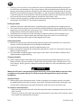
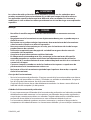
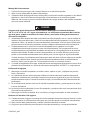
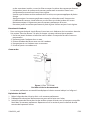
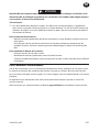
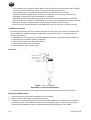
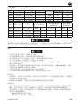
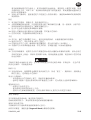
Controls
Blow
Neutral
1. Collaring
2. Half
Throttle
3. Full
Throttle
Figure 1. (Dwg. 16578304)
Operating Lever Positions
The jackhamer is controlled by moving the lever as shown in Figure 1.
Operating the Tool
1. Connect the leader hose to the air connection on the jackhamer.
2. Open the latch by pushing the lever down.
3. Insert the shank end of the drill steel in the front-head, and swing the latch up to lock the
tool in the jackhamer.
CAUTION
Make sure the tool is the correct size for front-head: 7/8” x 3-1/4”, 7/8” x 4-1/4” or 1” x 4-1/4”
depending on the chuck. Don’t use a jackhamer tool that is worn; it won’t do an eective
job and will cause unnecessary wear to the jackhamer.
4. Immediately after starting the jackhamer, check for the presence of oil mist at the exhaust
port and on the drill steel shank. This is the only assurance that oil is travelling all the way
through the jackhamer. When checking the jackhamer for lubrication, always put the tool
against the work.
•
1.
2.
3.
4.
5.
•

EN-6 51985323_ed5
EN
5. Heating is not unusual in a new jackhamer and it should be checked carefully during the
rst few hours of operation. In most cases, heating will be localized around the piston stem
bearing at the front end of the cylinder. Test this area frequently with the hand. As long as
the hand can be held on the part comfortably, it is safe to continue drilling. When the heat
is great enough to cause discomfort, stop the jackhamer and let it cool. Since lack of oil can
cause excessive heating, check again to see that the steel shank is oily.
6. If exhaust freeze-up occurs, add anti-freeze lubricant directly through the air inlet
connection. Use “KILFROST” anti-freeze or equivalent.
Drilling the Hole
7. Hold the jackhamer with both hands, spread feet apart, and apply a rm steady pressure.
8. The correct amount of pressure for maximum drilling eciency can be gained only through
experience, but generally the correct pressure is usually recognizable by the rhythmic sound
of the exhaust and the free rotation of the steel.
9. Insucient pressure will cause the jackhamer to bounce and may crack carbide inserts.
10. Too much pressure will slow down the jackhamer and may result in a stuck drill steel.
11. Keep the jackhamer, drill steel and hole aligned at all times.
Collaring the Hole
12. When starting the hole, hold the jackhamer rmly against the work and use a steel short
enough so that the jackhamer can be handled comfortably.
13. Open the throttle gradually and drill at half throttle or less.
14. Make sure the bit is through the overburden and about 2 inches (51 mm) deep in the rock
before using full throttle.
15. The jackhamer should be kept at right angles to the work, until the hole is collared, then
repositioned for angled drilling.
Cleaning the Hole
16. Always keep the hole clean and free of cuttings by blowing the hole frequently or using
plenty of water with wet machines. The bit must work on fresh rock. If the bit churns in its
own cuttings, drilling speed is reduced, and the possibility of a drill steel becoming stuck is
increased.
CAUTION
When the drill steel is not penetrating the rock freely, severe loads build up on the clutch
assembly causing overheating. This leads to major damage of these parts and early
breakdown.
Stuck Drill Steel
17. When drilling moist formations there is often a tendency for cuttings to pack in the hole
immediately behind the bit, forming a “mud collar.” Through action of the rotating bit, wet
cuttings pack solidly against the wall of the holes; and can cause a stuck drill steel.
To remove a stuck drill steel:
Remove the jackhamer from the stuck drill steel and make an attempt to loosen the steel
with a wrench.
Do not try to pull a stuck drill steel with the jackhamer for more than a few minutes. Heavy
thrust loads can damage front end parts.
-
-

51985323_ed5 EN-7
EN
To prevent a stuck drill steel:
Blow the hole often.
Keep the jackhamer working against fresh rock.
Raise the bit from the bottom of the hole, and blow the hole clean before removing drill
steel and bit.
Parts and Maintenance
When the life of the tool has expired, it is recommended that the tool be disassembled,
degreased and parts be separated by material so that they can be recycled.
Original instructions are in English. Other languages are a translation of the original instructions.
Tool repair and maintenance should only be carried out by an authorized Service Center.
Refer all communications to the nearest Ingersoll Rand Oce or Distributor.
-
-
-

ES-1 51985323_ed5
ES
Información de seguridad sobre el producto
Uso indicado:
El martillo rompedor de la Serie JH40 es capaz de perforar agujeros de 2 inch (51 mm) de
diámetro hasta 18 ft. (5.5 m) de profundidad en roca mediana a dura. Es particularmente
apropiada para labores de construcción, labores medianas de mantenimiento industrial, y para
las labores de utilidad en canteras y minas.
Para más información, consulte el Manual de información de seguridad de producto
04584975 Herramienta percutora neumática de gran formato.
Los manuales pueden descargarse en ingersollrandproducts.com
Installación y lubricación
Diseñe la línea de suministro de aire para asegurar la máxima presión de funcionamiento
(PMAX) en la entrada de la herramienta. Vacíe el condensado de las válvulas en los puntos
inferiores de la tubería, ltro de aire y depósito del compresor de forma diaria. Instale una
contracorriente de manguera de fusil de aire de seguridad de tamaño adecuado y utilice
un dispositivo antilatigazos en cualquier acoplamiento de manguera sin apagador interno
para evitar que las mangueras den latigazos en caso de que una manguera falle o de que el
acoplamiento se desconecte. Consulte la dibujo 16572133 y la tabla en la página 2. La frecuencia
de mantenimiento se muestra en forma de echa circular y se dene como h=horas, d=días y
m=meses. Los elementos se identican como:
1. Filtro de aire 6. Tamaño de la rosca
2. Regulador 7. Dispositivo de seguridad
3. Lubricador 8. Aceite
4. Válvula de corte de emergencia 9. Fusil de aire de seguridad
5. Diámetro de la manguera
Suministro de aire y conexiones
Use siempre aire limpio y seco. El polvo, los gases corrosivos y el exceso de humedad pueden
estropear una herramienta neumática. El uso de un ltro en la manguera de aire puede
aumentar considerablemete la vida útil de una herramienta neumática. El ltro elimina el polvo
y la humedad.
Utilice una manguera de calidad diseñada para uso con perforadores de roca. Las mangueras
para perforadores de roca se fabrican con una funda exterior resistente al desgaste por abrasión
y un tubo interno resistente al aceite que soporta el calor del aire comprimido. Las mangueras
de calidad tienen un factor de seguridad mínimo de presión de trabajo de 4:1 respecto a la
posibilidad de reventar.
Al utilizar una manguera nueva de aire comprimido, haga pasar aire lubricado por la misma un
tiempo suciente para que el interior quede totalmente revestido de aceite.
ADVERTENCIA
Conecte los cables de seguridad a los acoplamientos y accesorios de la manguera e instale
los pernos o elementos de bloqueo en el acoplamiento para evitar que las mangueras de
aire den latigazos.

51985323_ed5 ES-2
ES
Antes de conectar la manguera a la herramienta, haga pasar aire por la manguera principal de
aire comprimido para eliminar la humedad, las partículas de goma y la suciedad.
ADVERTENCIA
El aire comprimido es peligroso. Al purgar una manguera de aire, sostengala rmemente
y apuntela en la direccion opuesta del personal y del equipo. Jamas quite el polvo de su
vestimenta con aire comprimido.
Antes de conectar la manguera de aire a la conexión de aire, vierta .06 a .09 L (2 a 3 oz.) de aceite
de perforación de piedra en la entrada.
La herramienta se despacha de fabrica con una rosca macha de admision de 3/4 NPT.
Asegurese de que todos los racores y mangueras sean del tamano correcto y esten bien apretados.
El Esq. 16572133 (y la tabla en la página 2) muestra una disposicion caracteristica de las tuberias.
Requistos de aire
Se requiere un compresor de aire de capacidad suciente como para proporcionar el volumen
de aire necesario para alcanzar la pre-sión de funcionamiento de mayor eciencia, asegurando
así el funcionamiento ecaz y económico del martillo rompedor.
Los requisitos de aire representan pre-siones de aire en la entrada del martillo rompedor y no en
el compresor. Siempre existe cierta cantidad de caída de presión entre el compresor y el martillo
rompedor. Sólo la presión y volumen en la herramienta es ecaz al des-empeñar labores. Si la
manguera es relativamente corta y en buen estado, la caída de presión entre el compresor (o el
receptor de aire) y el martillo rompedor no debe sobrepasar el 15 por ciento de la presión inicial.
Una presión de aire baja o inadecuada en el martillo rompedor resulta costosa y derrochadora, y
un volumen de aire insuciente no le permitirá funcionar ecientemente.
AVISO
La lubricación apropiada es el factor más importante responsable de la vida de servicio del
martillo rompedor. Un martillo rompedor puede quedar seriamente dañado durante los
primeros cuantos minutos de funcionamiento si no se le lubrica debidamente.
La lubricación indebida impedirá el índice debido de rotación y acabará por reducir
la velocidad de rotación. El uso prolongado del martillo rompedor sin la lubricación
adecuada ocasionará daños a la unidad.
Utilice siempre un lubricador de aire comprimido con estas herramientas.
Instale el lubricador a unos 3,5 m de la herramienta.
Al principio de cada turno de ocho horas y una vez durante el turno, llene de aceite
recomendado el lubricador de aire comprimido.
Antes de llenar un depósito, limpie la zona alrededor del tapón de llenado.
Ajuste el lubricador de aire comprimido para que produzca una capa delgada de aceite en el
vástago de la barrena del taladro. Si sale humo azul del escape o se escurre aceite por la barrena,
es señal de un exceso de lubricación. Para empezar a ajustarla, gire a derechas la válvula de
aguja del lubricador hasta que quede cerrada. Gire la válvula a izquierdas 3/4 de vuelta para
obtener un punto inicial. Gire la válvula en un sentido u otro hasta que se obtenga la cantidad
de lubricación deseada. Al comprobar la lubricación apoye siempre la herramienta contra la
supercie a romper.
Al utilizar un lubricador montado en el compresor, la longitud de la manguera no debe

ES-3 51985323_ed5
ES
exceder de 15 m.
Si se congela el escape, añada lubricante anticongelante directamente por la entrada de aire. Use
lubricante “KILFROST” o uno equivalente.
Guarde todos los aceites en envases cubiertos en una zona relativamente libre de polvo para
evitar que se contaminen.
Especicaciones para el aceite de perforación de piedra
Características
Procedimiento
de prueba
32°C (90°F)
y temperaturas
inferiores
Sobre 32°C
(90°F)
Viscosidad:
SUS at 100°F (38°C) ASTM-D2161 175 Min. 450 Min.
SUS at 210°F (99°C) ASTM-D2161 46 Min. 65 Min.
cST at 104°F (40°C) ASTM-D445 37 Min. 105 Min.
cST at 212°F (100°C) ASTM-D445 6 Min. 11 Min.
Punto de fusión, °F (°C) Max. ASTM-D97 -10°F (-23°C) -10°F (-23°C)
Punto de ignición, °F (°C) Max. ASTM-D92 370°F (188°C) 400°F (204°C)
Indice de viscosidad, Min. ASTM-D2270 90 90
No. de emulsión vaporosa, Min. ASTM-1935-65 1200 1200
Consistencia --- Fibroso Fibroso
Prueba de carga Falex kg (lb) [Min.] ASTM-D2670 2000 lbs. (907 kg) 2000 lbs. (907 kg)
Prueba de carga Timken E.P. kg (lb) [Min] ASTM-D2782 30 lbs. (14 kg) 30 lbs. (14 kg)
Especicaciones
Modelo
Diámetro
del cilindro
Carrera
Tamaño
emmangadura (ex.)
Peso
(Neto)
Consumo de aire
at 90 psi (6.2 bar)
Impactos
por
minuto
I.D. pulg. (mm) pulg. (mm) pulg. lbs (kg) ft
3
/min. m
3
/min.
JH40C1 2.5 (63.5) 2-5/8 (66.7) 7/8 x 3-1/4 61 (27.7) 115 3.25 2000
JH40C2 2.5 (63.5) 2-5/8 (66.7) 7/8 x 4-1/4 61 (27.7) 115 3.25 2000
JH40C3 2.5 (63.5) 2-5/8 (66.7) 1 x 4-1/4 61 (27.7) 115 3.25 2000
Modelo
Longitud total
(sin herramienta)
Presión de aire
recomendada en
la admisión
Nivel Sonoro dB (A)
(ISO15744)
Vibración
(m/s
2
)
(ISO28927)
I.D. pulg. (mm) psig bar † Presión (L
p
)
‡ Potencia (L
w
)
Nivel *K
JH40C1 22.5 (572) 90 - 100 6.2 - 6.9 -- -- -- --
JH40C2 22.5 (572) 90 - 100 6.2 - 6.9 -- -- -- --
JH40C3 22.5 (572) 90 - 100 6.2 - 6.9 -- -- -- --
† KpA = 3dB de error * K = de error (Vibración)
‡ KwA = 3dB de error

51985323_ed5 ES-4
ES
ADVERTENCIA
Los valores de ruido y vibración se han medido de acuerdo con los estándares para
pruebas reconocidos internacionalmente. Es posible que la exposición del usuario en
una aplicación especíca de herramienta diera de estos resultados. Por lo tanto, la
mediciones in situ se deberían utilizar para determinar el nivel de riesgo en esa aplicación
especíca.
Manejo
CUIDADO
No utilice el martillo rompedor cuando la herramienta no se encuentre contra en
material.
No golpee nunca la herramienta con un objeto contundente, pues se puede romper o
dañar la carcasa.
No intente nunca realizar trabajos importantes de mantenimiento de la herramienta
sobre la marcha; llévela a un taller de reparación.
No arrastre nunca la herramienta por el suelo, pues las lumbreras de aire del escape
pueden llenarse de suciedad.
Utilice aire comprimido para despejar de suciedad la manguera de aire antes de
conectarla a la herramienta.
Asegúrese de que la herramienta esté bien lubricada.
En temperaturas extremadamente frías, mantenga las herramientas del martillo
rompedor envueltas en arpillera o tela hasta inmediatamente antes de utilizarlos.
A los -18°C (0°F) una herramienta de acero endurecido pierde un 80% de su resistencia
normal a los choques.
Conserve siempre insertados en todas las lumbreras los tapones o capuchones de
plástico mientras la herramienta no esté en uso.
No levante ni lleve la herramienta sujetándola por la palanca de mando, o se podrá
dañar la herramienta.
Consejos de Funcionamiento
Revise la herramienta de perforación. El agujero central de la herramienta debe estar abierto,
y las espigas de broca deben ser planas y cuadradas, no astilladas o redondeadas. Asegúrese
que la espiga de la herramienta sea de la extensión debida.
Asegúrese que las brocas hayan sido debidamente amoladas. Las brocas romas dicultan la
labor del martillo rompedor y la del operario.
Cuidado de la herramienta de perforacion
Es muy importante que el leteado de la herramienta de perforación sea lubricado y atendido
debidamente en todo momento. Las herramientas con leteados desgastados, agrietados o
corrosión por rozamiento no deben ser utilizados. También debe tenerse cuidado durante la
perforación de no doblar la herramienta o co-rroer el leteado debido al mal uso.
Las herramientas dobladas producen tensiones innecesarias y aceleran el desgaste de los
componentes del cabezal delantero. Las herramientas dobladas y la corrosión por rozamiento
•
•
•
•
•
•
•
•
•
•
•
•
•

ES-5 51985323_ed5
ES
pueden ser evitadas si se toman las siguientes medidas:
Asegúrese que la herramienta haya fondeado en la broca.
Todos los leteados deben estar en buen estado y bien lubricados.
Siempre perfore con una broca alada. Las brocas romas pueden ocasionar un
golpamiento excesivo y tensiones innecesarias en todos los leteados y piezas del martillo
rompedor.
No se acerque jamás a la piedra con el martillo en funcionamiento. Posicione con cuidado
y tome bocados del agujero con poca aceleración. Una vez que la broca haya tomado
bocados de la piedra, puede aplicarse la marcha plena.
Mantenga siempre el martillo rompedor contra el material. La insuciencia de presión de
alimentación hará que la broca se aoje sobre la herramienta, dañando los leteados y
haciendo que las piezas insertas se desgarren.
Mantenga siempre el alineamiento entre el martillo rompedor y el agujero.
Jamás retracte el martillo rompedor a marcha plena. Utilice media marcha.
Cuidado de la broca
Para prolongar la vida útil de la broca, las instrucciones de cuidado de la barrena del taladro
deben aplicarse también a la broca. Deben tomarse los siguientes pasos adicionales también:
Jamás permita que la broca quede atascada con cortaduras sueltas. Purgue el agujero
constantemente.
Jamás fuerce o trate de espetar la broca dentro de un agujero.
Quite la broca del acero con una llave para brocas.
Jamás golpee la broca con un martillo.
Jamás accione una broca roma.
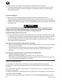
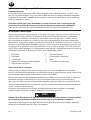
Controls
Soplado
Neutral
1. Bocados
2. Media
potencia
3. Toda
Marcha
Figura 1. (Esq. 16578304)
Colocaciones de la Planca de Funcionamiento
El martillo rompedor está controlado mediante el movimiento de la planca como lo ilustra la
Figura 1.
-
-
-
-
-
-
-
•
1.
2.
3.
4.
5.
•

51985323_ed5 ES-6
ES
Manejo de la herramienta
1. Conecte la manguera guía a la conexión de aire en el martillo rompedor.
2. Abra el cierre empujando la palanca hacia abajo.
3. Coloque el lado de espiga de la herramienta de inserción del martillo rompedor en el cabezal
delantero, y tire el cierre hacia arriba para jar la herramienta en el martillo rompedor.
Reérase a la Sección 6, para los tamaños debidos de espigas de broca del martillo rompedor
que está siendo utilizado.
CUIDADO
Asegurese de que la herramiento sea del tamaño debido para el cabezal delantero:
7/8” x 3-1/4” o 7/8” x 4-1/4” segun el portabrocas. no utilice una herramiento de insercion
que este roma, ya que no realizara una labor ecaz y ocasionara el desgaste innecesario
del martillo rompedor.
4. Inmediatamente después de haber activado el martillo rompedor, revise si existe neblina de
aceite en el puerto de escape y sobre la herramienta del martillo rompedor. Esta es la única
manera de saber si el aceite está recorriendo todo el neumático. Al revisar que la lubricación
correcta existe en el martillo rompedor, siempre coloque la herramienta contra el material.
5.
El calentamiento no es inusual en un martillo rompedor nuevo y deberá ser revisado
cuidadosamente durante las primeras horas de funcionamiento. En la mayoría de los casos,
el calentamiento estará localizado alrededor del cojinete de vástago del pistón en el extremo
delantero del cilindro. Pruebe esta área frecuentemente con la mano. Mientras que la mano
pueda ser mantenida cómodamente contra dicha parte, resulta seguro el seguir perforando.
Cuando el calor es lo sucientemente fuerte como para ocasionar malestar, detenga el martillo
rompedor y déjelo enfriar. Puesto que la falta de aceite puede ocasionar un calentamiento
excesivo, vuelva a revisar para ver si la herramienta inserta se encuentra aceitosa.
6.
Si sucede la congelación del escape, añada lubricante anticoagulante directamente a través de la
conexión de la entrada de aire. Utilice el lubricante anticoagulante “KILFROST” o su equivalente.
Perforando el agujero
7. Mantenga el martillo rompedor con ambas manos, aparte sus pies, y aplique una presión
rme y constante.
8. La cantidad de presión adecuada para la eciencia máxima durante la perforación puede
obtenerse solamente por medio de la experiencia, pero por lo general, la pre-sión indicada
puede reconocerse por el sonido rítmico del escape y la rotación libre de la herramienta de
perforación.
9. La insuciencia de presión hará que el martillo rompedor rebote, y puede agrietar las piezas
insertas de carburo.
10. La presión excesiva detendrá el marti-llo rompedor, y puede resultar en el atascamiento de la
herramienta de perforación.
11. Mantenga el martillo rompedor, la he-rramienta y el agujero alineados en todo momento.
Hechura de “bocados” del agujero
12.
Cuando comience el agujero, mantenga el martillo rompedor rmemente contra el material y utilice
una herramienta lo sucientemente corta para que el martillo pueda ser manejado cómodamente.
13. Abra el acelerador gradualmente y perfore a media aceleración o menos.
14. Asegúrese que la broca haya atravesado la tierra de descombro y a una profundidad de

ES-7 51985323_ed5
ES
unos 51mm (2”) en la piedra antes de utilizar la aceleración a toda marcha.
15. El martillo rompedor debe ser mantenido a ángulos rectos con respecto al material hasta
que se hayan tomado los bocados del agujero, y es entonces vuelto a posicionar para la
perforación angulada.
Limpieza del agujero
16. Mantenga siempre limpio el agujero y libre de cortaduras purgando el agujero
frecuentemente o utilizando agua abundante con las máquinas mojadas. La broca debe
trabajar sobe piedra fresca. Si la broca se bate dentro de sus propias cortaduras, la velocidad
de perforación queda reducida, y aumenta la posibilidad de que la herramienta de inserción
quede atascada.
CUIDADO
Cuando la herramienta no este penetrando la piedra libremente, se acumulan cargas
severas sobre el ensamblado del embrague, ocasionando el sobrecalentamiento. Esto
conduce a las averias serias de dichas piezas y al fallo prematuro.
Herramienta de perforacion atascada
17. Durante la perforación de formaciones húmedas existe a menudo la tendencia por parte de
las cortaduras de amontonarse en el agujero inmediatamente detrás de la broca, formando
un “collar de lodo”. A través de la acción de la broca rotativa, las cortaduras mojadas se
aglutinan sólidamente contra las paredes de los agujeros, y pueden ocasionar la atascadura
de una herramienta de perforación.
Para quitar una herramienta de perforación atascada:
Retire el martillo rompedor de la he-rramienta de perforación y haga el intento de aojar la
herramienta con una llave.
No trate de extraer la herramienta atascada con el martillo rompedor por más de unos
cuantos minutos. Las cargas de empuje axial pueden dañar las piezas del extremo
delantero.
Para impedir el atascamiento de una herramienta de perforación:
Purgue el agujero con frecuencia.
Mantenga el martillo rompedor funcionando contra la piedra fresca.
Eleve la broca del fondo del agujero y purgue el agujero hasta que quede limpio antes de
sacar la herramienta de perforación y las brocas.
Piezas y mantenimiento
Una vez vencida la vida útil de herramienta, se recomienda desarmar la herramienta,
desengrasarla y separar las piezas de acuerdo con el material del que están fabricadas para
reciclarlas.
OLas instrucciones originales están en inglés. Las demás versiones son una traducción de las
instrucciones originales.
Las labores de reparación y mantenimiento de las herramientas sólo puede ser realizadas por un
Centro de Servicio Autorizado.
Toda comunicación se deberá dirigir a la ocina o al distribuidor Ingersoll Rand más próximo.
-
-
-
-
-

51985323_ed5 FR-1
FR
Informations de sécurité du produit
Utilisation prévue:
Le Serie marteau-perforateur est capable de forer des trous de 2” (51 mm) jusqu’à 18 ft. (5.5 m)
de profondeur dans de la roche moyenne ou dure. Il est particulièrement adapté aux travaux
de construction, aux travaux de maintenance moyenne dans l’industrie et aux travaux d’utilité
générale dans les carrières et dans les mines.
Pour des informations complémentaires, reportez-vous au manuel 04584975
d’information de sécurité du produit Air Percussive Drill.
Les manuels peuvent être téléchargés à l’adresse ingersollrandproducts.com
Installation et lubrication
Dimensionnez l’alimentation en air de façon à obtenir une pression maximale (PMAX) au niveau
de l’entrée d’air de l’outil. Drainez quotidiennement le condensat des vannes situées aux points
bas de la tuyauterie, du ltre à air et du réservoir du compresseur. Installez un raccordement à
air de sûreté dont la taille est adaptée au tuyau et placez-le en amont de celui-ci, puis utilisez
un dispositif anti-débattement sur tous les raccords pour tuyaux sans fermeture interne, an
d’empêcher les tuyaux de fouetter si l’un d’entre eux se décroche ou si le raccord se détache.
Reportez-vous à l’illustration 16572133 et au tableau de la page 2. Les intervalles d’entretien sont
indiqués à l’aide d’une èche circulaire et dénis à l’aide de lettres (h = heures, d = jours et
m =mois). Eléments identiés en tant que:
1. Filtre à air 6. Taille du letage
2. Régulateur 7. Raccord et de sécurité
3. Lubricateur 8. Huile
4. Vanne d’arrêt d’urgence 9. Raccordement à air de sûreté
5. Diamètre du tuyau
Alimentation et raccords d’air comprimé
Utiliser toujours de l’air comprimé propre et sec. La poussière, les fumées corrosives et/ou une
humidité excessive peuvent endommager un outil pneumatique. Un ltre d’air comprimé peut
nettement prolonger la durée de vie d’un outil pneumatique. Le ltre élimine les poussières et
l’humidité.
Utiliser des exibles de qualité conçus spécialement pour le forage des roches. Le exible de
forage de roche est construit avec un revêtement extérieur résistant à l’usure par abrasion et un
tube intérieur résistant à l’huile et à la chaleur de l’air comprimé. Le coecient de sécurité du
exible de qualité est tel que la pression d’éclatement est au moins égale à quatre fois la pression
de travail.
Pour un exible d’air neuf, faire circuler de l’air lubrié dans le exible pendant un temps
susamment long pour enduire d’huile tout l’intérieur.
AVERTISSEMENT
Fixez les câbles de sécurité sur les raccords et couplages des exibles et installez les
goupilles d’arrêt ou épingles de verrouillage de sécurité sur le couplage de manière à
éviter le fouettement des exibles d’air.

FR-2 51985323_ed5
FR
Chasser par souage toute l’humidité, les particules de caoutchouc et les saletés du exible d’air
comprimé avant de l’attacher à l’outil.
AVERTISSEMENT
L’air comprimé est dangereux. Au moment de purger une ligne d’air, tenez-la fermement
et visez loin de toute personne et de tout matériel. Ne jamais enlever la poussière de vos
vêtements avec de l’air comprimé.
Avant de relier la ligne d’air à sa connexion, verser 60 à 90 ml (2 à 3 on.) d’huile pour perforatrice
dans l’entrée d’air.
L’outil est expédié de l’usine avec un raccord d’entrée mâle leté de 3/4 NPT.
Vérier que tous les tuyaux exibles et raccords sont correctement dimensionnés. Voir Plan
16572133 et au tableau de la page 2 pour un exemple type d’agencement des tuyauteries.
Besoins en air
Il faut un compresseur d’air capable de fournir le volume d’air nécessaire avec la pression la plus
adaptée, pour travailler de manière ecace et économique avec le marteau-perforateur.
Les besoins en air représentent les pressions d’air prises au niveau de l’entrée du
marteau-perforateur et non du compresseur. Il y a toujours une perte de pression entre le
compresseur et le marteau-perforateur et ce ne sont que les pression et volume au niveau de
l’outil qui sont eectifs dans le travail. Si la ligne est relativement courte et en bonne condition,
la perte de pression entre le compresseur (ou le récepteur d’air) et le marteauperforateur ne
devrait pas excéder 15% de la pression initiale.
Une pression d’air faible ou inadaptée au niveau du marteau-perforateur est coûteuse et peu
rentable, et un volume d’air insusant ne permettra pas de travailler ecacement.
AVIS
Une lubrication correcte est le facteur le plus déterminant de la durée de vie d’un
marteauperforateur pneumatique. Un marteau-perforateur peut être sérieusement
endomagé dès les premières minutes d’utilisation s’il n’est pas correctement lubrié.
Une lubrication inadaptée empêche une bonne rotation et nalement réduit la vitesse
de rotation.
Une utilisation prolongée du marteau-perforateur sans une lubrication adaptée
provoque des dommages à l’appareil.
Utiliser toujours un lubricateur avec ces outils.
Installer le lubricateur à environ 3,5 m de l’outil.
Au début de chaque poste de huit heures et une fois pendant le poste, remplir le
lubricateur d’air comprimé avec de l’huile recommandée.
Nettoyer la zone autour du bouchon de remplissage avant de remplir n’importe quel réservoir.
Ajuster le lubricateur d’air comprimé de manière à obtenir un léger lm d’huile à la queue du
euret. Une lubrication excessive est indiquée par une fumée bleue à l’échappement ou des
fuites d’huile le long du euret. Commencer le réglage en tournant la soupape à pointeau du
lubricateur à fond dans le sens des aiguilles d’une montre pour la fermer. Tourner la soupape
de 3/4 de tour dans le sens inverse des aiguilles d’une montre comme réglage de départ initial.
Tourner la soupape dans un sens ou dans l’autre jusqu’à ce que la lubrication souhaitée soit
obtenue. Toujours placer l’outil contre la surface de travail pour vérier la lubrication.

51985323_ed5 FR-3
FR
Lorsqu’un lubricateur monté sur le compresseur est utilisé, la longueur du exible ne doit
pas dépasser 15 m.
En cas de gel de l’échappement, ajouter du lubriant antigel directement dans l’admission d’air.
Utiliser le lubriant “KILFROST” ou équivalent.
Stocker toutes les huiles dans des récipients fermés et dans une zone relativement exempte de
poussière pour éviter toute contamination.
Spécications des huiles de perforatrice
Caractéristique
Procédure de
test
90°F et moins
(32°C et moins)
Au dessus de 32°C
(90°F)
Viscosité:
SUS à 100°F (38°C) ASTM-D2161 175 Min. 450 Min.
SUS à 210°F (99°C) ASTM-D2161 46 Min. 65 Min.
cST à 104°F (40°C) ASTM-D445 37 Min. 105 Min.
cST à 212°F (100°C) ASTM-D445 6 Min. 11 Min.
Point de fusion maximal °F (°C) ASTM-D97 -10°F (-23°C) -10°F (-23°C)
Point éclair maximal °F (°C) ASTM-D92 370°F (188°C) 400°F (204°C)
Index de viscosité minimal ASTM-D2270 90 90
Nombre minimum d’émulsion en vapeur ASTM-1935-65 1200 1200
Consistance --- visqueuse visqueuse
Test Falex en charge kg (livres) [min] ASTM-D2670 907 kg (2000 livres) 907 kg (2000 livres)
Test Timken E.P. kg (livres) [min] ASTM-D2782 30 lbs. (14 kg) 30 lbs. (14 kg)
Spécications du produit
Modèle
Alésage
du
cylindre
Course utile
Taille du
mandrin
(Hexagonal)
Coups
par
minute
Consommation
d’air
at 90 psi (6.2 bar)
Poids
(nett)
I.D. inch (mm) inch (mm) inch ft
3
/min.
m
3
/
min.
lbs (kg)
JH40C1 2.5 (63.5) 2-5/8 (66.7) 7/8 x 3-1/4 2000 115 3.25 61 (27.7)
JH40C2 2.5 (63.5) 2-5/8 (66.7) 7/8 x 4-1/4 2000 115 3.25 61 (27.7)
JH40C3 2.5 (63.5) 2-5/8 (66.7) 1 x 4-1/4 2000 115 3.25
Modèle
Longueur
totale
Alimentation d’air
recommandée à
l’entrée
Niveau Sonore dB (A)
(ISO15744)
Vibrations (m/s
2
)
(ISO28927)
I.D. inch (mm) psig bar
† Pressure (L
p
) ‡ Puissance (L
w
) Niveau *K
JH40C1 22.5 (572) 90 - 100 6.2 - 6.9 -- -- -- --
JH40C2 22.5 (572) 90 - 100 6.2 - 6.9 -- -- -- --
JH40C3 22.5 (572) 90 - 100 6.2 - 6.9 -- -- -- --
† KpA = incertitude de mesure de 3dB * K = incertitude de mesure (Vibration)
‡ KwA = incertitude de mesure de 3dB

FR-4 51985323_ed5
FR
AVERTISSEMENT
Les valeurs sonores et vibratoires ont été mesurées dans le respect des normes de tests
reconnues au niveau international. L’exposition de l’utilisateur lors d’une application
d’outil spécique peut diérer de ces résultats. Par conséquent, il faut utiliser des mesures
sur site an de déterminer le niveau de risque de cette application spécique.
Fonctionnement
ATTENTION
Ne faites pas fonctionner le marteau-perforateur quand l’outil n’est pas contre la surface
de travail.
Ne jamais exploiter l’outil lorsque le euret ou le bloc de marteau n’est pas contre la
surface de travail.
Ne jamais frapper l’outil avec un objet épointé sous peine de fracture ou
d’endommagement du corps.
Ne jamais entreprendre des opérations majeures d’entretien de l’outil sur le chantier ; le
coner à un atelier de réparation.
Ne jamais traîner l’outil sur le sol ; les orices d’air de l’échappement pourraient se
remplir de saletés.
Nettoyer toujours le exible d’alimentation d’air avant de le connecter à l’outil pour
évacuer toutes les saletés qui pourraient se trouver dans le exible.
Vérier que l’outil est correctement lubrié.
Par temps extrêmement froid, conservez le euret enveloppé dans de la toile de jute ou
un chion jusqu’à l’utilisation. A -18°C (0°F) un outil en acier trempé perd environ 80%
de sa résistance normale aux chocs.
Obturer toujours tous les orices avec des capuchons ou des bouchons en plastique
lorsque l’outil n’est pas en service.
Ne jamais soulever ou transporter l’outil par son levier de commande. L’outil peut être
endommagé.
Conseils d’exploitation
Vériez le euret. Le trou central du euret doit être ouvert et la queue doit être plate et
carrée, sans éclat ni arrondi. Vériez que la queue du euret est de la bonne longueur.
Vériez bien que les embouts sont correctement aûtés. Des embouts émoussés sont
nuisibles au marteau-perforateur et à l’opérateur.
Entretien du euret
Il est très important que les lets du euret soient lubriés correctement et entretenus en
permanence. Les eurets avec des lets rayés, des ssures ou des usures importantes ne
doivent pas être utilisés. Aussi, un soin particulier sera prêté pendant la perforation an de ne
pas plier le euret ou user les lets à cause d’une mauvaise utilisation.
Un euret faussé engendre des contraintes inutiles et accélère l’usure des éléments de tête.
Un euret faussé et une usure importante des lets peuvent être évités en respectant les
étapes suivantes :
Vériez que le euret est bien emboîté dans l’embout.
Tous les lets doivent être en bon état et bien lubriés.
Perforez toujours avec un embout aiguisé. Un embout usé engendre une charge excessive
•
•
•
•
•
•
•
•
•
•
•
•
•
•
-
-
-
A página está carregando ...
A página está carregando ...
A página está carregando ...
A página está carregando ...
A página está carregando ...
A página está carregando ...
A página está carregando ...
A página está carregando ...
A página está carregando ...
A página está carregando ...
A página está carregando ...
A página está carregando ...
A página está carregando ...
A página está carregando ...
A página está carregando ...
A página está carregando ...
A página está carregando ...
A página está carregando ...
A página está carregando ...
A página está carregando ...
-
 1
1
-
 2
2
-
 3
3
-
 4
4
-
 5
5
-
 6
6
-
 7
7
-
 8
8
-
 9
9
-
 10
10
-
 11
11
-
 12
12
-
 13
13
-
 14
14
-
 15
15
-
 16
16
-
 17
17
-
 18
18
-
 19
19
-
 20
20
-
 21
21
-
 22
22
-
 23
23
-
 24
24
-
 25
25
-
 26
26
-
 27
27
-
 28
28
-
 29
29
-
 30
30
-
 31
31
-
 32
32
-
 33
33
-
 34
34
-
 35
35
-
 36
36
-
 37
37
-
 38
38
-
 39
39
-
 40
40


