Sparky MB 1600C HD Manual do usuário
- Categoria
- Ferramentas elétricas
- Tipo
- Manual do usuário
Este manual também é adequado para

www.sparky.eu
1706R01 142321V4© 2017 SPARKY
1010W
1300/1600 W
M 1010 HD • MB 1010 HD • MB 1010PA HD
M 1300 HD • MB 1300 HD • MB 1300PA HD • MB 1600C HD • MB 1600CPA HD
1 – 11
ANGLE GRINDER
Original instructions
24 – 36
MEULEUSE ANGULAIRE
Notice originale
87 – 100
УГЛОШЛИФОВАЛЬНАЯ МАШИНА
Оригинальная инструкция по эксплуатации
12 – 23
WINKELSCHLEIFER
Originalbetriebsanleitung
Оригінальна інструкція з експлуатації
101 – 113
КУТОШЛІФУВАЛЬНА МАШИНА
75 – 86
SZLIFIERKA KĄTOWA
Oryginalna instrukcja obsługi
62 – 74
REBARBADORA ANGULAR
Manual original
37 – 48
SMERIGLIATRICE ANGOLARE
Istruzioni originali
49 – 61
ESMERILADORA ANGULAR
Instrucciones de uso originales
Оригинална инструкция за използване
114 – 127
ЪГЛОШЛИФОВЪЧНА МАШИНА
6 March 2017
Manufacturer
SPARKY Power Tools GmbH
Leipziger Str. 20
10117 Berlin, GERMANY
Signature of authorized person
A. Ivanov
Technical director of SPARKY ELTOS AD
DECLARATION OF CONFORMITY
We declare under our sole responsibility that this product, described under “Technical specications”, fulls all the relevant provisions of the
following directives and the harmonized standards: 2006/42/ЕС, 2014/30/EU, 2011/65/EU,
EN 60745-1, EN 60745-2-3; EN 55014-1, EN 55014-2, EN 61000-3-2, EN 61000-3-3, EN 50581.
Technical le is stored at SPARKY ELTOS AD, Kubrat Str. 9, 5500 Lovech, Bulgaria.
KONFORMITÄTSERKLÄRUNG
Hiermit versichern wir unsere persönliche Haftung, dass Produkt im Abschnitt “Technische Daten“ beschrieben“ allen einschlägigen
Bestimmungen folgender Richtlinien und entsprechender harmonisierten Standards entspricht: 2006/42/ЕС, 2014/30/EU, 2011/65/EU,
EN 60745-1, EN 60745-2-3; EN 55014-1, EN 55014-2, EN 61000-3-2, EN 61000-3-3, EN 50581.
Die technischen Unterlagen werden bei SPARKY ELTOS AD, Kubrat Str.9, 5500 Lovech, Bulgarien, aufbewahrt.
DECLARATION DE CONFORMITE
Nous déclarons sous notre responsabilité que le produit décrit dans la rubrique “Données techniques” satisfait à l’ensemble des dispositions
pertinentes des présentes directives, respectivement aux normes harmonisées: 2006/42/CЕ, 2014/30/UE, 2011/65/UE,
EN 60745-1, EN 60745-2-3; EN 55014-1, EN 55014-2, EN 61000-3-2, EN 61000-3-3, EN 50581.
Le dossier technique est conservé par SPARKY ELTOS AD, 9, rue Kubrat, 5500 Lovech, Bulgarie.
DICHIARAZIONE DI CONFORMITÀ
Noi dichiariamo sotto la nostra personale responsabilità, che il prodotto, descritto nella sezione “Dati tecnici” è in conformità a tutte le disposizioni
pertinenti della presente direttive e norme armonizzate: 2006/42/CЕ,2014/30/UE, 2011/65/UE,
EN 60745-1, EN 60745-2-3; EN 55014-1, EN 55014-2, EN 61000-3-2, EN 61000-3-3, EN 50581.
Il fascicolo tecnico viene custodito presso la SPARKY ELTOS AD, 5500 Lovech, via Kubrat n. 9, Bulgaria.
DECLARACIÓN DE CONFORMIDAD
Declaramos bajo nuestra exclusiva responsabilidad que el producto, descrito en los “Datos técnicos”, está conforme con todas las disposiciones
aplicables de la presente directrices aplicables y las correspondientes normas armonizadas: 2006/42/CЕ, 2014/30/UE, 2011/65/UE,
EN 60745-1, EN 60745-2-3; EN 55014-1, EN 55014-2, EN 61000-3-2, EN 61000-3-3, EN 50581.
El expediente técnico está archivado en SPARKY ELTOS AD, C/ Kubrat, 9, 5500 Lovech, Bulgaria.
DECLARAÇÃO DE CONFORMIDADE
Declaramos assumindo a nossa responsabilidade pessoal que el producto, descrito en los “Dados técnicos”, está conforme com todas as
disposições relevantes da presente directrizes aplicáveis e respectivos estandartes harmonizados: 2006/42/CЕ, 2014/30/UE, 2011/65/UE,
EN 60745-1, EN 60745-2-3; EN 55014-1, EN 55014-2, EN 61000-3-2, EN 61000-3-3, EN 50581.
A documentação técnica guarda-se no SPARKY ELTOS AD, rua Kubrat 9, 5500, Lovech, Bulgária.
DEKLARACJA ZGODNOŚCI
Niniejszym deklarujemy naszą osobistą odpowiedzialnością, że produkt, przedstawiony w rozdziale „Dane techniczne“, pełnia wszystkie
odpowiednie postanowienia następujących dyrektyw i harmonizowanych standardów: 2006/42/WЕ, 2014/30/UE, 2011/65/UE,
EN 60745-1, EN 60745-2-3; EN 55014-1, EN 55014-2, EN 61000-3-2, EN 61000-3-3, EN 50581.
Teczka techniczna przechowywana jest w SPARKY ELTOS AD, Kubrat Str.9, 5500 Lovetch, Bułgaria.
ДЕКЛАРАЦИЯ О СООТВЕТСТВИИ
Мы заявляем со всей ответственностью, что продукт, описанный в разделе “Технические данные“, полностью соответствует всем
соответствующим требованиям действующих директив и гармонизированных стандартов: 2006/42/ЕС, 2014/30/EU, 2011/65/EU,
EN 60745-1, EN 60745-2-3; EN 55014-1, EN 55014-2, EN 61000-3-2, EN 61000-3-3, EN 50581.
Техническое досье хранится в СПАРКИ ЕЛТОС АД, ул. Кубрат №9, 5500 Ловеч, Болгария.
ДЕКЛАРАЦІЯ ПРО ВІДПОВІДНІСТЬ
Ми заявляємо під свою власну відповідальність, що продукт, описаний у розділі “Teхнічні дані“ відповідає всім діючим вимогам директив і
гармонізованих стандартів: 2006/42/ЕС, 2014/30/EU, 2011/65/EU,
EN 60745-1, EN 60745-2-3; EN 55014-1, EN 55014-2, EN 61000-3-2, EN 61000-3-3, EN 50581.
Технічне досьє зберігається в СПАРКИ ЕЛТОС АД, ул. Кубрат № 9, 5500 Ловеч, Болгарія.
ДЕКЛАРАЦИЯ ЗА СЪОТВЕТСТВИЕ
Ние декларираме на своя лична отговорност, че изделието, описано в раздел “Технически данни”, отговаря на всички приложими
изисквания на следните директиви и хармонизирани стандарти: 2006/42/ЕС, 2014/30/EU, 2011/65/EU,
EN 60745-1, EN 60745-2-3; EN 55014-1, EN 55014-2, EN 61000-3-2, EN 61000-3-3, EN 50581.
Техническото досие се съхранява в СПАРКИ ЕЛТОС АД, ул. Кубрат №9, 5500 Ловеч, България.
BLACK PANTONE185
BLACK PANTONE185

BА
5 6 7
1
2b
L
3
6
7
91
4
5
8
2.1 3.1
10
11
12
13
4
3.1
2.1
5
4
3.2
2.2
5
4
2a
BLACK PANTONE185
BLACK PANTONE185

1
EN
Introduction
Your new SPARKY power tool will more than satisfy your expectations. It has been manufactured
under stringent SPARKY Quality Standards to meet superior performance criteria. You will nd your
new tool easy and safe to operate, and, with proper care, it will give you many years of dependable
service.
WARNING:
Carefully read through these Original Instructions before using your new SPARKY power tool.
Take special care to heed the Warnings. Your SPARKY power tool has many features that will
make your job faster and easier. Safety, performance, and dependability have been given top
priority in the development of this tool, making it easy to maintain and operate.
Do not dispose of electric tools together with household waste!
Waste electrical products should not be disposed of with household waste. Please recycle
where facilities exist. Check with your local authority or retailer for recycling advice.
ENVIRONMENTAL PROTECTION
The machine, accessories and packaging should be sorted for environmental-friendly
recycling.
The plastic components are labelled for categorised recycling.
UNPACKING
Due to modern mass production techniques, it is unlikely that your power tool is faulty or that a part is
missing. If you nd anything wrong, do not operate the tool until the parts have been replaced or the
fault has been rectied. Failure to do so could result in serious personal injury.
ASSEMBLY
The angle grinder is packed fully assembled except for the wheel guard and the auxiliary handle.
Contents
Introduction ............................................................................................................................... 1
Technical specications ............................................................................................................3
General power tool safety warnings ..........................................................................................4
Angle grinder safety warnings ...................................................................................................5
Know your product .................................................................................................................A/8
Operation ...............................................................................................................................B/8
Maintenance ...........................................................................................................................10
Warranty .................................................................................................................................. 11
M 1010 HD● MB 1010 HD ● MB 1010PA HD ● M 1300 HD ● MB 1300 HD
MB 1300PA HD ● MB 1600C HD ● MB 1600CPA HD● Original instructions

2
EN
M 1010 HD ● MB 1010 HD ● MB 1010PA HD ● M 1300 HD
MB 1300 HD ● MB 1300PA HD ● MB 1600C HD ● MB 1600CPA HD
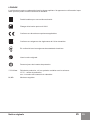
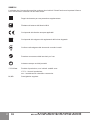
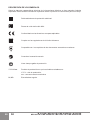
DESCRIPTION OF SYMBOLS
The rating plate on your power tool may show symbols. These represent important information about
the product or instructions on its use.
Double insulated for additional protection.
Spindle thread: M14
Conforms to the relevant European Directives.
Conforms to the requirements of Customs Union regulations.
Conforms to the requirements of Ukrainian standards.
Refer to Original Instructions.
Always wear eye protection.
YYYY-Www Production period, where the variable symbols are:
YYYY- year of manufacture,
ww - calendar week number.
M, MB Angle grinder.

3
Original instructions
EN
The vibration emission level given in this information sheet has been measured in accordance with
a standardised test given in EN 60745 and may be used to compare one tool with another. It may be
used for a preliminary assessment of exposure.
The declared vibration emission level represents the main applications of the tool. However if the tool
is used for different applications, with different accessories or poorly maintained, the vibration emis-
sion may differ. This may signicantly increase the exposure level over the total working period.
An estimation of the level of exposure to vibration should also take into account the times when the
tool is switched off or when it is running but not actually doing the job. This may signicantly reduce
the exposure level over the total working period.
Maintain the power tool and the accessories and keep your hands warm during operation to reduce
the harmful effect of vibrations.
Other applications such as cutting-off or wire brushing may have different vibration emission values.
Dust from material such as paint containing lead, some wood species, minerals and metal may be
harmful. Contact with or inhalation of the dust may cause allergic reactions and/or respiratory dis-
eases to the operator or bystanders.
Certain kinds of dust are classied as carcinogenic such as oak and beech dust especially in conjunc-
tion with additives for wood conditioning (chromate, wood preservative). Material containing asbestos
must only be treated by specialists.
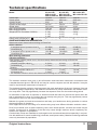
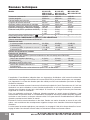
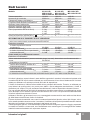
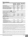
Technical specications
Model M 1010 HD M 1300 HD MB 1600C HD
MB 1010 HD MB 1300 HD MB 1600CPA HD
MB 1010PA HD MB 1300PA HD
Power input 1010 W 1300 W 1600 W
Rated speed 9500 min
-1
9500 min
-1
9500 min
-1
Spindle thread M14 M14 M14
Spindle thread length 20 mm 20 mm 20 mm
Wheel arbor 22.23 mm 22.23 mm 22.23
Max. wheel diameter 150 mm 150 mm 150 mm
Max. wheel thickness 10 mm 10 mm 10 mm
Weight (ЕРТА Procedure 01/2014) 3.3 kg 3.6 kg 3.6 kg
3.3 kg 3.6 kg 3.7 kg
3.4 kg 3.7 kg
Safety class (EN 60745-1) II II II
NOISE AND VIBRATION INFORMATION
Measured values determined according to EN 60745.
Noise emission
A-weighted sound pressure level L
pA
92 dB(A) 93 dB(A) 93 dB(A))
Uncertainty К
pA
3.0 dB 3.0 dB 3.0 dB
A-weighted sound power level L
wA
103 dB(A) 104 dB(A) 104 dB(A))
Uncertainty К
wA
3.0 dB 3.0 dB 3.0 dB
Wear hearing protection!
Vibration emission *
Total vibration values (vector sum in the three axes) determined according to EN 60745:
Surface grinding
Vibration emission value a
h,AG
4.8 m/s
2
4.6 m/s
2
4.8 m/s
2
Uncertainty К
AG
1.5 m/s
2
1.8 m/s
2
1.8 m/s
2
Sanding
Vibration emission value a
h,DS
7.0 m/s
2
7.2 m/s
2
7.0 m/s
2
Uncertainty К
DS
1.8 m/s
2
1.8 m/s
2
1.8 m/s
2
* The vibration emission values are determined according to 6.2.7 EN 60745.

4
EN
M 1010 HD ● MB 1010 HD ● MB 1010PA HD ● M 1300 HD
MB 1300 HD ● MB 1300PA HD ● MB 1600C HD ● MB 1600CPA HD
General power tool
safety warnings
WARNING! Read all safety warn-
ings and all instructions. Failure to follow
the warnings and instructions may result in
electric shock, re and/or serious injury.
Save all warnings and instructions for
future reference.
The term “power tool” in the warnings refers
to your mains-operated (corded) power tool or
battery-operated (cordless) power tool.
1) Work area safety
a) Keep work area clean and well lit. Clut-
tered or dark areas invite accidents.
b) Do not operate power tools in explosive
atmospheres, such as in the presence
of ammable liquids, gases or dust.
Power tools create sparks which may ignite
the dust or fumes.
c) Keep children and bystanders away
while operating a power tool. Distrac-
tions can cause you to lose control.
2) Electrical safety
a) Power tool plugs must match the outlet.
Never modify the plug in any way. Do
not use any adapter plugs with earthed
(grounded) power tools. Unmodied
plugs and matching outlets will reduce risk
of electric shock.
b) Avoid body contact with earthed or
grounded surfaces, such as pipes, ra-
diators, ranges and refrigerators. There
is an increased risk of electric shock if your
body is earthed or grounded.
c) Do not expose power tools to rain or wet
conditions. Water entering a power tool
will increase the risk of electric shock.
d) Do not abuse the cord. Never use the
cord for carrying, pulling or unplugging
the power tool. Keep cord away from
heat, oil, sharp edges or moving parts.
Damaged or entangled cords increase the
risk of electric shock.
e) When operating a power tool outdoors,
use an extension cord suitable for out-
door use. Use of a cord suitable for out-
door use reduces the risk of electric shock.
f) If operating a power tool in a damp lo-
cation is unavoidable, use a residual
current device (RCD) protected supply.
Use of an RCD reduces the risk of electric
shock.
3) Personal safety
a) Stay alert, watch what you are doing
and use common sense when operating
a power tool. Do not use a power tool
while you are tired or under the inu-
ence of drugs, alcohol or medication.
A moment of inattention while operating
power tools may result in serious personal
injury.
b) Use personal protective equipment.
Always wear eye protection. Protective
equipment such as dust mask, non-skid
safety shoes, hard hat, or hearing protec-
tion used for appropriate conditions will re-
duce personal injuries.
c) Prevent unintentional starting. Ensure
the switch is in the off-position before
connecting to power source and/or bat-
tery pack, picking up or carrying the
tool. Carrying power tools with your nger
on the switch or energising power tools that
have the switch on invites accidents.
▪ Where the use of a dust extraction device is possible it shall be used.
▪ The work place must be well ventilated.
▪ The use of a dust mask of lter class P2 is recommended.
Follow national requirements for the materials you want to work with.
All models with Index B are equipped with electronic device for soft start and restriction of starting
current to 16 A.
Models with index P feature safety upon mains drop-out. In case of mains drop-out or unplugging for
more than 0.5 s the power tool remains switched off and can be started only after switching off and
on the ON/OFF switch.
All models with index C in the abbreviation feature no load speed limitation and rpm stabilization upon
loading.
All models with index A at the end of the abbreviation are equipped with anti-vibration back handle.

5
Original instructions
EN
d) Remove any adjusting key or wrench be-
fore turning the power tool on. A wrench
or a key left attached to a rotating part of
the power tool may result in personal in-
jury.
e) Do not overreach. Keep proper footing
and balance at all times. This enables
better control of the power tool in unexpect-
ed situations.
f) Dress properly. Do not wear loose cloth-
ing or jewellery. Keep your hair, cloth-
ing and gloves away from moving parts.
Loose clothes, jewellery or long hair can be
caught in moving parts.
g) If devices are provided for the connec-
tion of dust extraction and collection fa-
cilities, ensure these are connected and
properly used. Use of dust collection can
reduce dust-related hazards.
4) Power tool use and care
a) Do not force the power tool. Use the cor-
rect power tool for your application. The
correct power tool will do the job better and
safer at the rate for which it was designed.
b) Do not use the power tool if the switch
does not turn it on and off. Any power tool
that cannot be controlled with the switch is
dangerous and must be repaired.
c) Disconnect the plug from the power
source and/or the battery pack from the
power tool before making any adjust-
ments, changing accessories, or stor-
ing power tools. Such preventive safety
measures reduce the risk of starting the
power tool accidentally.
d) Store idle power tools out of the reach
of children and do not allow persons
unfamiliar with the power tool or these
instructions to operate the power tool.
Power tools are dangerous in the hands of
untrained users.
e) Maintain power tools. Check for mis-
alignment or binding of moving parts,
breakage of parts and any other condi-
tion that may affect the power tool’s op-
eration. If damaged, have the power tool
repaired before use. Many accidents are
caused by poorly maintained power tools.
f) Keep cutting tools sharp and clean.
Properly maintained cutting tools with
sharp cutting edges are less likely to bind
and are easier to control.
g) Use the power tool, accessories and
tool bits etc. in accordance with these
instructions, taking into account the
working conditions and the work to be
performed. Use of the power tool for op-
erations different from those intended could
result in a hazardous situation.
5) Service
a) Have your power tool serviced by a
qualied repair person using only iden-
tical replacement parts. This will ensure
that the safety of the power tool is main-
tained.
Angle grinder safety
warnings
Safety Warnings Common for Grinding,
Sanding, Wire Brushing or Abrasive
Cutting-Off Operations:
a) This power tool is intended to func-
tion as a grinder, sander, wire brush or
cut-off tool. Read all safety warnings,
instructions, illustrations and speci-
cations provided with this power tool.
Failure to follow all instructions listed below
may result in electric shock, re and/or seri-
ous injury.
b) This power tool is not recommended for
polishing. Operations for which the power
tool was not designed may create a hazard
and cause personal injury.
c) Do not use accessories which are
not specically designed and recom-
mended by the tool manufacturer. Just
because the accessory can be attached to
your power tool, it does not assure safe op-
eration.
d) The rated speed of the accessory must
be at least equal to the maximum speed
marked on the power tool. Accessories
running faster than their rated speed can
break and y apart.
e) The outside diameter and the thickness
of your accessory must be within the
capacity rating of your power tool. In-
correctly sized accessories cannot be ad-
equately guarded or controlled.
f) Threaded mounting of accessories
must match the grinder spindle thread.
For accessories mounted by anges,
the arbour hole of the accessory must
t the locating diameter of the ange.
Accessories that do not match the mount-
ing hardware of the power tool will run out
of balance, vibrate excessively and may
cause loss of control.
g) Do not use a damaged accessory. Be-

6
EN
M 1010 HD ● MB 1010 HD ● MB 1010PA HD ● M 1300 HD
MB 1300 HD ● MB 1300PA HD ● MB 1600C HD ● MB 1600CPA HD
fore each use inspect the accessory
such as abrasive wheels for chips and
cracks, backing pad for cracks, tear or
excess wear, wire brush for loose or
cracked wires. If power tool or acces-
sory is dropped, inspect for damage or
install an undamaged accessory. After
inspecting and installing an accessory,
position yourself and bystanders away
from the plane of the rotating accessory
and run the power tool at maximum no-
load speed for one minute. Damaged ac-
cessories will normally break apart during
this test time.
h) Wear personal protective equipment.
Depending on application, use face
shield, safety goggles or safety glasses.
As appropriate, wear dust mask, hearing
protectors, gloves and workshop apron
capable of stopping small abrasive or
workpiece fragments. The eye protection
must be capable of stopping ying debris
generated by various operations. The dust
mask or respirator must be capable of l-
trating particles generated by your opera-
tion. Prolonged exposure to high intensity
noise may cause hearing loss.
i) Keep bystanders a safe distance away
from work area. Anyone entering the
work area must wear personal protec-
tive equipment. Fragments of workpiece
or of a broken accessory may y away and
cause injury beyond immediate area of op-
eration.
j) Hold the power tool by insulated grip-
ping surfaces only, when performing an
operation where the cutting accessory
may contact hidden wiring or its own
cord. Cutting accessory contacting a “live”
wire may make exposed metal parts of the
power tool “live” and could give the opera-
tor an electric shock.
k) Position the cord clear of the spinning
accessory. If you lose control, the cord
may be cut or snagged and your hand or
arm may be pulled into the spinning acces-
sory.
l) Never lay the power tool down until the
accessory has come to a complete stop.
The spinning accessory may grab the sur-
face and pull the power tool out of your con-
trol.
m) Do not run the power tool while carrying
it at your side. Accidental contact with the
spinning accessory could snag your cloth-
ing, pulling the accessory into your body.
n) Regularly clean the power tool’s air
vents. The motor’s fan will draw the dust
inside the housing and excessive accumu-
lation of powdered metal may cause electri-
cal hazards.
o) Do not operate the power tool near am-
mable materials. Sparks could ignite these
materials.
p) Do not use accessories that require
liquid coolants. Using water or other liq-
uid coolants may result in electrocution or
shock.
▪ The tool must be used only for its pre-
scribed purpose. Any use other use
than those mentioned in this Instruction
will be considered a case of misuse. The
user and not the manufacturer shall be li-
able for any damage or injury resulting from
such cases of misuse.
▪ The manufacturer shall not be liable for
any changes made to the tool nor for any
damage resulting from such changes.
▪ When operating in dusty environment,
the ventilation slots must be kept clean.
If it should become necessary to clear
dust, rst disconnect the tool from the
mains supply (use non metallic objects
to clean the dust) and avoid damaging
internal parts. The power tool will over-
heat under deteriorated cooling due to the
clogged with dust ventilation slots.
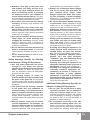
Further safety instructions for all opera-
tions
Kickback and Related Warnings
Kickback is a sudden reaction to a pinched or
snagged rotating wheel, backing pad, brush
or any other accessory. Pinching or snagging
causes rapid stalling of the rotating accessory
which in turn causes the uncontrolled power tool
to be forced in the direction opposite of the ac-
cessory’s rotation at the point of the binding.
For example, if an abrasive wheel is snagged or
pinched by the workpiece, the edge of the wheel
that is entering into the pinch point can dig into
the surface of the material causing the wheel to
climb out or kick out. The wheel may either jump
toward or away from the operator, depending on
direction of the wheel’s movement at the point of
pinching. Abrasive wheels may also break under
these conditions.
Kickback is the result of power tool misuse and/
or incorrect operating procedures or conditions
and can be avoided by taking proper precau-
tions as given below.

7
Original instructions
EN
a) Maintain a rm grip on the power tool
and position your body and arm to al-
low you to resist kickback forces. Al-
ways use auxiliary handle, if provided,
for maximum control over kickback or
torque reaction during start-up. The oper-
ator can control torque reactions or kickback
forces, if proper precautions are taken.
b) Never place your hand near the rotating
accessory. Accessory may kickback over
your hand.
c) Do not position your body in the area
where power tool will move if kickback
occurs. Kickback will propel the tool in di-
rection opposite to the wheel’s movement
at the point of snagging.
d) Use special care when working corners,
sharp edges etc. Avoid bouncing and
snagging the accessory. Corners, sharp
edges or bouncing have a tendency to
snag the rotating accessory and cause loss
of control or kickback.
e) Do not attach a saw chain woodcarving
blade or toothed saw blade. Such blades
create frequent kickback and loss of con-
trol.
▪ Fix the machined piece in vice or in an-
other appropriate way.
Safety Warnings Specic for Grinding
and Abrasive Cutting-Off Operations:
a) Use only wheel types that are recom-
mended for your power tool and the
specic guard designed for the selected
wheel. Wheels for which the power tool
was not designed cannot be adequately
guarded and are unsafe.
b) The grinding surface of centre de-
pressed wheels must be mounted below
the plane of the guard lip. An improperly
mounted wheel that projects through the
plane of the guard lip cannot be adequately
protected.
c) The guard must be securely attached
to the power tool and positioned for
maximum safety, so the least amount of
wheel is exposed towards the operator.
The guard helps to protect operator from
broken wheel fragments, accidental con-
tact with wheel and sparks that could ignite
clohting.
d) Wheels must be used only for recom-
mended applications. For example: do
not grind with the side of cut-off wheel.
Abrasive cut-off wheels are intended for
peripheral grinding, side forces applied to
these wheels may cause them to shatter.
e) Always use undamaged wheel anges
that are of correct size and shape for
your selected wheel. Proper wheel
anges support the wheel thus reduc-
ing the possibility of wheel breakage.
Flanges for cut-off wheels may be different
from grinding wheel anges.
f) Do not use worn down wheels from larg-
er power tools. Wheel intended for larger
power tool is not suitable for the higher
speed of a smaller tool and may burst.
▪ Always pay attention to the wheel rota-
tion direction. The torque reaction is in the
opposite direction of the rotation direction
at the point of binding and this is a prereq-
uisite to loosing control of the power tool.
▪ Always guide the machine in such a way
that sparks and dust can scatter away
from your body. Power tools generate
sparks which may burn your clothes or un-
protected parts of your body.
▪ Grinding and cutting-off operations on
freshly painted metal structures is not
allowed before the paint has become
dry. There is a risk of damp paint ignition.
▪ Cutting of ammable materials (wood,
plastics, etc.) and panel structures
“sandwich” type with ammable lling
is not allowed. There is a risk of re.
▪ Grinding and cutting-off operations on
equipment operating under pressure is
not allowed. There is a risk of explosion.
▪ Grinding and cutting-off operations of
reservoirs, pipelines, equipment, etc.,
containing at present or having con-
tained ammable or easily ignitable
substances or materials is not allowed
without rst taking special precautions
to prevent re and explosion. There is a
risk of re and explosion.
Additional Safety Warnings Specic for
Abrasive Cutting-Off Operations:
a) Do not “jam” the cut-off wheel or apply
excessive pressure. Do not attempt to
make an excessive depth of cut. Over-
stressing the wheel increases the loading
and susceptibility to twisting or binding of
the wheel in the cut and the possibility of
kickback or wheel breakage.
b) Do not position your body in line with
and behind the rotating wheel. When the
wheel, at the point of operation, is moving
away from your body, the possible kickback
may propel the spinning wheel and the

8
EN
M 1010 HD ● MB 1010 HD ● MB 1010PA HD ● M 1300 HD
MB 1300 HD ● MB 1300PA HD ● MB 1600C HD ● MB 1600CPA HD
power tool directly at you.
c) When wheel is binding or when inter-
rupting a cut for any reason, switch off
the power tool and hold the power tool
motionless until the wheel comes to a
complete stop. Never attempt to remove
the cut-off wheel from the cut while the
wheel is in motion otherwise kickback
may occur. Investigate and take corrective
action to eliminate the cause of wheel bind-
ing.
d) Do not restart the cutting operation in
the workpiece. Let the wheel reach full
speed and carefully re-enter the cut. The
wheel may bind, walk up or kickback if the
power tool is restarted in the workpiece.
e) Support panels or any oversized work-
piece to minimize the risk of wheel
pinching and kickback. Large workpiec-
es tend to sag under their own weight.
Supports must be placed under the work-
piece near the line of cut and near the
edge of the workpiece on both sides of the
wheel.
f) Use extra caution when making a “pock-
et cut” into existing walls or other blind
areas. The protruding wheel may cut gas
or water pipes, electrical wiring or objects
that can cause kickback.
Safety Warnings Specic for Sanding
Operations:
a) Do not use excessively oversized sand-
ing disc paper. Follow manufacturer’s
recommendations, when selecting
sanding paper. Larger sanding paper ex-
tending beyond the sanding pad presents
a laceration hazard and may cause snag-
ging, tearing of the disc or kickback.
Safety Warnings Specic for Wire
Brushing Operations:
a) Be aware that wire bristles are thrown
by the brush even during ordinary op-
eration. Do not overstress the wires by ap-
plying excessive load to the brush. The wire
bristles can easily penetrate light clothing
and/or skin.
b) If the use of a guard is recommended for
wire brushing, do not allow any interfer-
ence of the wire wheel or brush with the
guard. Wire wheel or brush may expand in
diameter due to work load and centrifugal
forces.
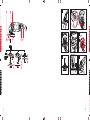
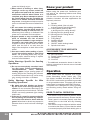
Know your product
Before using the power tool, familiarize your-
self with all the operating features and safety
requirements.
Use the tool and accessories only for the ap-
plications intended. All other applications are
expressly ruled out.
1. Spindle
2.1. Grinding wheel (Use only with
a wheel guard for grinding wheel!)*
2.2. Cutting wheel (Use only with
a wheel guard for cutting wheel!)*
3.1. Wheel guard for grinding wheel
3.2. Wheel guard for cutting wheel*
4. Support ange
5. Fixing ange
6. Auxiliary handle
7. ON/OFF switch
8. ON/OFF switch locking button
9. Spindle lock button
ACCESSORIES TO BE USED WITH
THIS POWER TOOL
10. Wire cup brush*
11. Plastic (rubber) backing pad*
12. Sandpaper*
13. Lock nut*
* The additional accessories shown in the illus-
trations or described in the text are not included
in the delivery.
Operation
These power tools are supplied from single-
phase alternating current mains only. They
are double insulated according to EN 60745,
IEC 60745-1 and can be connected to grounded
or not grounded sockets. This power tool is radio
suppressed in compliance with EMC Directive.
This power tool is designed for cutting, grinding
and brushing mainly metals without using wa-
ter.
PRIOR TO INITIAL OPERATION
▪ The machine may be delivered with the wheel
guard mounted at the factory. Ensure that the
wheel guard is mounted properly and xed
reliably prior to the initial and any following
operation.
▪ The machine may be delivered with the wheel
mounted at the factory. Ensure that the wheel
is mounted properly and xed reliably prior to

9
Original instructions
EN
the initial and any following operation.
▪ Make sure the power supply voltage corre-
sponds to the value indicated on the name
plate with technical data of the tool.
▪ Always check the position of ON/OFF switch.
The power tool must be connected and dis-
connected to the power supply socket only
when this switch is in OFF position. If the plug
is connected to a receptacle while the power
switch is in the ON position, the power tool
will start operating immediately, which could
cause a serious accident.
▪ Make sure that the cord and the plug are in
order. If the replacement of the supply cord is
necessary, this has to be done by the manu-
facturer or his agent in order to avoid a safety
hazard.
WARNING: Always switch off and un-
plug the power tool prior to any adjustment,
servicing or maintenance.
▪ When using diamond cutting discs, pay atten-
tion that the direction-of-rotation arrow on the
diamond cutting disc and the direction of rota-
tion of the machine (see direction-of-rotation
arrow on the machine head) agree.
▪ Make sure the grinding wheel diameter and
thickness do not exceed the values specied
on the name plate. The peripheral speed in-
dicated on the wheel must not be less than
80 m/s. The wheels must be stored according
the recommendations of the manufacturer.
▪ In case the work area is remote from the pow-
er source, use as short as practicable exten-
sion cord with proper cross-section.
▪ Check that the auxiliary handle is properly
mounted and reliably tightened.
SWITCHING ON - SWITCHING OFF
The angle grinder is secured against uninten-
tional switching on.
▪ Switching on: First push forward the auxiliary
button 8 positioned at the bottom of the main
handle, then press ON/OFF switch 7. For
continuous operation switch 7 can be locked.
In this case while holding switch 7, press but-
ton 8 and then release switch 7.
▪ Switching off: Release switch 7; in case the
switch is locked, rst press and then release
that switch.
WHEEL GUARD
WARNING: The wheel guard 3.1 for
grinding wheel or the wheel guard 3.2 for
cutting wheel (for grinding wheel 2.1 or cut-
ting wheel 2.2 accordingly) must always be
mounted on the machine!
WARNING: Before performing the fol-
lowing operations, switch off and unplug the
machine.
Mounting the wheel guard (Fig. 1)
- Rotate the black plastic ring (Fig. 2a), so
that the crevice S of the ring coincides with the
groove for the tooth of the xing lever L.
- Place the wheel guard in non-operating
position (Fig.2a) so that the four teeth coin-
cide with the four grooves in the bearing seat
(Fig.2b).
- Press the fastening lever L (g.3) to re-
lease it.
- Press the wheel guard down and rotate it
in the necessary operating position (Fig.4).
- Release the fastening lever L to a stable
position in which the wheel guard is xed (the
xing lever tooth enters into one of the guard
grooves).
Rotating the wheel guard in a new operat¬ing
position
- Press the fastening lever L (Fig.3) to re-
lease it.
- Rotate the wheel guard to the necessary
operating position.
- Release the fastening lever L to a stable
position in which the wheel guard is xed (the
xing lever tooth enters into one of the guard
grooves).
Removing the wheel guard
- Press the fastening lever L (Fig.3) to re-
lease it.
- Rotate the wheel guard in non-operating
position (Fig.2a) so that the four teeth coin-
cide with the four grooves in the bearing seat
(Fig.2b).
- Remove the wheel guard.

10
EN
M 1010 HD ● MB 1010 HD ● MB 1010PA HD ● M 1300 HD
MB 1300 HD ● MB 1300PA HD ● MB 1600C HD ● MB 1600CPA HD
GRINDING WHEEL REPLACEMENT
WARNING: Before performing the fol-
lowing operations, switch off and unplug the
machine.
Secure spindle 1 by pressing the spindle lock
button 9 on the gear case.
WARNING: Never press button 9
while the spindle is still rotating!
▪ With this button depressed rotate the wheel
in direction opposite to the arrow marked on
the wheel guard 3 until it has profoundly gone
deeper. Unscrew xing ange 5 by a special
wrench. Place the new wheel on the sup-
port ange 4 with the inscriptions facing up,
and screw down ange 5 using the lock nut
wrench. Use blotters if the wheel has been
delivered with them. If the wheel thickness is
less then 6 mm, place the xing ange 5 with
its at side towards the wheel. If the wheel is
thicker than 6 mm, place the xing ange 5
to the spindle so that the ange step enters
the wheel opening. After replacing the wheel,
operate the machine with the new wheel in
no load mode for one minute. Vibrating or
otherwise improperly rotating wheels must be
replaced immediately and discarded.
▪ The cup brush 10 is screwed directly on
spindle 1 by means of an open-end wrench.
Check if the brush thread length is sufcient
to accept the spindle thread.
▪ Grinding with sandpaper is performed with
plastic (rubber) backing pad 11, under which
sandpaper 12 is fastened. Place the exible
backing pad 11 onto the support ange 4 and
fasten it with the lock nut 13, delivered with
the tool. In case the exible backing pad is
equipped with a ange nut, the pad is screwed
directly onto the spindle by a wrench without
using the xing ange 5. The pad with ange
may be a resin lled sponge, polyurethane
foam sponge with plastic insert for the ange
with hook-and-loop fastening to the sandpa-
per. After replacing the wheel, operate the
machine with the new backing pad in no load
mode for one minute. Vibrating or otherwise
improperly rotating backing pads must be re-
placed immediately and discarded.
AUXILIARY HANDLE (Fig.5)
Normally auxiliary handle 6 is screwed on the
machine left side. It can be screwed also on
the machine right side or top if this is more
convenient for the operator. The machines are
equipped with a third threaded socket for cou-
pling the auxiliary handle. The auxiliary handle
for these models is connected to the body of the
machine through vibration dampers, protecting
the operator and reducing fatigue.
TURNING THE MACHINE CASE
The machine case can be turned to 90
0
. This
way of mounting is implemented when the ma-
chine is used mainly for cutting-off operations.
In this case turning the machine case must be
carried out in an authorized service centre for
SPARKY power tools.
RECOMMENDATIONS
When cutting, do not apply pressure, do not os-
cillate the wheel. Work with moderate feed rate,
suited to the material to be machined.
The direction of cutting is very signicant. The
machine must always be fed against the direc-
tion of wheel rotation. Otherwise, danger exists
for the wheel to be forced uncontrolled out of the
cut. (Fig. 6)
When cutting proles or rectangular pipes it is
best to start with the smallest cross section.
When grinding do not apply pressure to the
processed surface by rearing down on the ma-
chine but move the wheel regularly backwards
and forwards. Special wheels shall be used for
processing non-ferrous metals. Best results
when roughing can be achieved with the wheel
inclined at 30
0
to 40
0
to the processed surface
(Fig. 7).
Never use cutting wheels for roughing opera-
tions. Usage of wheels thicker than 10 mm is
not recommended.
Maintenance
WARNING: Always ensure that the
tool is switched off and unplugged before
attempting to perform inspection or mainte-
nance.

11
Original instructions
EN
BRUSH REPLACEMENT
This power tool is equipped with auto-stop
brushes. When the carbon brushes are worn
out, the machine switches itself off. In this case
both brushes must be replaced simultaneously
with genuine brushes at SPARKY service centre
for warranty and post-warranty service.
GENERAL INSPECTION
Regularly inspect all fasteners and ensure they
are properly tightened. Should any of the screws
be loose, retighten it immediately to avoid haz-
ards.
If the replacement of the supply cord is neces-
sary, this has to be done by the manufacturer or
his agent in order to avoid a safety hazard.
CLEANING
For safe operation always keep the machine
and its ventilation slots clean.
Regularly check to see if any dust or foreign mat-
ter has entered the ventilation slots and the grills
around the switches. Use a soft brush and/or air
jet to remove any accumulated dust. Wear safety
glasses to protect your eyes whilst cleaning.
Exterior plastic parts may be cleaned with a
damp cloth and mild detergent if necessary.
WARNING: Never use alcohol, petrol
or other cleaning agent. Never use caustic
agents to clean plastic parts.
WARNING: Water must never come
into contact with the tool.
IMPORTANT! To assure product safety and re-
liability, repairs, maintenance and adjustment
(including brush inspection and replacement)
should be performed by certied service centres
or other qualied service organisations, always
using genuine replacement parts.
Warranty
The guarantee period for SPARKY power tools
is determined in the guarantee card.
Faults due to normal wear, overloading or im-
proper handling will be excluded from the guar-
antee.
Faults due to defective materials implemented
as well as defects in workmanship will be cor-
rected free of charge through replacement or
repair.
The complaints for defective SPARKY power
tools will be recognized if the machine is sent
back to the dealer or is presented to the author-
ised warranty service centre undismantled, in its
initial condition.
Notes
Carefully read through these Original Instruc-
tions before using this product.
The manufacturer reserves the right to make
changes and improvements to the products and
to alter specications without prior notice.
Specications may differ from country to coun-
try.

12
DE
M 1010 HD ● MB 1010 HD ● MB 1010PA HD ● M 1300 HD
MB 1300 HD ● MB 1300PA HD ● MB 1600C HD ● MB 1600CPA HD
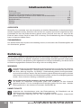
Inhaltsverzeichnis
Einführung ...............................................................................................................................12
Technische Daten ....................................................................................................................14
Allgemeine Sicherheitshinweise für Elektrowerkzeuge ............................................................15
Zusätzliche Anleitungen für Sicherheit bei Arbeiten mit Winkelschleifern ...............................17
Elemente des Elektrowerkzeugs ...........................................................................................A/20
Betriebshinweise ...................................................................................................................B/20
Wartung ...................................................................................................................................23
Garantie .................................................................................................................................. 23
Einführung
Das von Ihnen erworbene Elektrowerkzeug wird Ihre Erwartungen übersteigen. Es ist gemäß den ho-
hen Qualitätsstandards von SPARKY hergestellt, die den strengen Anforderungen des Verbrauchers
entsprechen. Einfach in der Bedienung und ungefährlich bei richtiger Handhabung, wird dieses Gerät
bei bestimmungsgemäßem Gebrauch Ihnen lange Jahre zuverlässig dienen.
WARNUNG!
Lesen Sie die ganze Originalbetriebsanleitung aufmerksam durch, bevor Sie das neu erworbene
SPARKY – Elektrowerkzeug in Betrieb nehmen. Beachten Sie besonders die Texte, die mit
dem Wört „Warnung“ beginnen. Ihr SPARKY - Elektrowerkzeug besitzt viele Eigenschaften,
die Ihre Arbeit erleichtern werden. Bei der Entwicklung dieses Elektrowerkzeuges ist höchste
Aufmerksamkeit der Sicherheit, den Betriebseigenschaften und der Zuverlässigkeit gewidmet
worden, die es einfach zur Wartung und Bedienung machen.
Keine elektrischen Geräte zusammen mit dem Hausmüll wegwerfen!
Die Abfälle von elektrischen Erzeugnissen sollen nicht zusammen mit dem Hausmüll
gesammelt werden. Für eine umweltgerechte Entsorgung geben Sie Ihren alten / defekten
Elektrogeräte bitte in der nächsten kommunalen Sammelstelle ab.
UMWELTSCHUTZ
Angesichts des Umweltschutzes sollen das Elektrowerkzeug, die Zubehörteile und die
Verpackung einer geeigneten Wiederverwertung zugeführt werden.
Zum sortenreinen Recycling sind die Teile, hergestellt aus Kunststoffen, entsprechend
gekennzeichnet.
AUSPACKEN
Überprüfen Sie unmittelbar nach dem Auspacken ob sämtliche Bestandteile und das beschriebene
Zubehör mitgeliefert wurden. Sollte dies nicht der Fall sein, wenden Sie sich bitte umgehend an Ihren
Fachhändler bei dem das Elektrowerkzeug gekauft wurde. Dies trifft auch dann zu, wenn Sie den
Eindruck haben mit dem Gerät ist etwas nicht in Ordnung. Eine Nichtbeachtung dieser Empfehlung
kann zu schweren Unfällen führen.
ZUSAMMENBAU
Der Winkelschleifer wird verpackt und vollständig montiert, mit Ausnahme des Zusatzhandgriffes und
der Schutzhaube, geliefert.

13
DE
Originalbetriebsanleitung
BEDEUTUNG DER SYMBOLE
Auf dem Typenschild des Elektrowerkzeuges sind spezielle Symbole dargestellt. Sie stellen wichtige
Information über das Produkt oder Instruktionen für seine Nutzung dar.
Doppelte Isolierung für zusätzlichen Schutz.
Spindelgewinde: M14
Entspricht den einschlägigen Europäischen Richtlinien.
Entspricht den Anforderungen der Zollunion-Regelungen.
Entspricht den Anforderungen der ukrainischen normativen Dokumenten.
Lesen Sie die Originalbetriebsanleitung.
Tragen Sie immer eine Schutzbrille.
YYYY-Www Zeitabschnitt der Produktion, wobei die variablen Symbole sind:
YYYY - Kalenderjahr der Produktion,
ww - laufende Kalenderwoche.
M, MB Winkelschleifer.

14
DE
M 1010 HD ● MB 1010 HD ● MB 1010PA HD ● M 1300 HD
MB 1300 HD ● MB 1300PA HD ● MB 1600C HD ● MB 1600CPA HD
Der in diesen Anweisungen angegebene Schwingungspegel ist entsprechend einem in EN 60745
genormten Messverfahren gemessen worden und kann für den Vergleich von Elektrowerkzeugen
miteinander verwendet werden. Er eignet sich auch für eine vorläuge Einschätzung der Schwin-
gungsbelastung.
Der angegebene Schwingungspegel repräsentiert die hauptsächlichen Anwendungen des Elektro-
werkzeugs. Wenn allerdings das Elektrowerkzeug für andere Anwendungen, mit abweichenden Ein-
satzwerkzeugen oder ungenügender Wartung eingesetzt wird, kann der Schwingungspegel abwei-
chen. Dies kann die Schwingungsbelastung über den gesamten Arbeitszeitraum deutlich erhöhen.
Für eine genaue Abschätzung der Schwingungsbelastung sollten auch die Zeiten berücksichtigt wer-
den, in denen das Gerät abgeschaltet ist oder zwar läuft, aber nicht tatsächlich im Einsatz ist. Dies
kann die Schwingungsbelastung über den gesamten Arbeitszeitraum deutlich reduzieren.
Pegen Sie das Gerät und die Einsatzwerkzeuge mit Sorgfalt. Halten Sie Ihre Hände warm während
der Arbeit - dies wird die schädliche Einwirkung erhöhter Schwingungen reduzieren.
Bei anderen Arbeiten, z.B. Schleifen mit Abrasivscheiben oder Reinigung mit Drahtbürste können die
Schwingungsemissionen auch andere Werte haben.
Stäube von Materialien wie bleihaltigem Anstrich, einigen Holzarten, Mineralien und Metall können
gesundheitsschädlich sein. Berühren oder Einatmen der Stäube können allergische Reaktionen und/
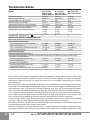
Technische Daten
Modell M 1010 HD M 1300 HD MB 1600C HD
MB 1010 HD MB 1300 HD MB 1600CPA HD
MB 1010PA HD MB 1300PA HD
Aufnahmeleistung 1010 W 1300 W 1600 W
Bemessungsdrehzahl 9500 min
-1
9500 min
-1
9500 min
-1
Anschlußgewinde der Spindel M14 M14 M14
Gewindelänge der Spindel 20 mm 20 mm 20 mm
Innendurchmesser der Schleifscheibe 22.23 mm 22.23 mm 22.23
Max Durchmesser der Schleifscheibe 150 mm 150 mm 150 mm
Max Stärke der Schleifscheibe 10 mm 10 mm 10 mm
Gewicht (ЕРТА Prozedur 01/2014) 3.3 kg 3.6 kg 3.6 kg
3.3 kg 3.6 kg 3.7 kg
3.4 kg 3.7 kg
Schutzklasse (EN 60745-1)
II II II
GERÄUSCH-/VIBRATIONSINFORMATION
Messwerte ermittelt entsprechend EN 60745.
Geräuschemissionswerte
Der A-bewertete Schalldruckpegel L
pA
92 dB(A) 93 dB(A) 93 dB(A))
Messunsicherheit К
pA
3.0 dB 3.0 dB 3.0 dB
Der A-bewertete Schalleistungspegel L
wA
103 dB(A) 104 dB(A) 104 dB(A))
Messunsicherheit К
wA
3.0 dB 3.0 dB 3.0 dB
Gehörschutz tragen!
Schwingungsemissionswerte *
Schwingungsgesamtwerte (Vektorsumme dreier Richtungen) ermittelt entsprechend EN 60745:
Schleifen von Oberächen
Schwingungsemissionswert a
h,AG
4.8 m/s
2
4.6 m/s
2
4.8 m/s
2
Messunsicherheit К
AG
1.5 m/s
2
1.8 m/s
2
1.8 m/s
2
Schleifen mit Schleieinen
Schwingungsemissionswert a
h,DS
7.0 m/s
2
7.2 m/s
2
7.0 m/s
2
Messunsicherheit К
DS
1.8 m/s
2
1.8 m/s
2
1.8 m/s
2
* Vibrationen ermittelt nach Pkt. 6.2.7 der EN 60745.

15
DE
Originalbetriebsanleitung
Allgemeine
Sicherheitshinweise
für Elektrowerkzeuge
WARNUNG: Lesen Sie alle Sicher-
heitshinweise und Anweisungen. Versäum-
nisse bei der Einhaltung der Sicherheitshin-
weise und Anweisungen können elektrischen
Schlag, Brand und/oder schwere Verletzun-
gen verursachen.
Bewahren Sie alle Sicherheitshinweise
und Anweisungen für die Zukunft auf.
Der in den Sicherheitshinweisen verwende-
te Begriff „Elektrowerkzeug“ bezieht sich auf
netzbetriebene Elektrowerkzeuge (mit Netzka-
bel) und auf akkubetriebene Elektrowerkzeuge
(ohne Netzkabel).
1) Arbeitsplatzsicherheit
a) Halten Sie Ihren Arbeitsbereich sauber
und gut beleuchtet. Unordnung oder un-
beleuchtete Arbeitsbereiche können zu Un-
fällen führen.
b) Arbeiten Sie mit dem Elektrowerkzeug
nicht in explosionsgefährdeter Umge-
bung, in der sich brennbare Flüssigkei-
ten, Gase oder Stäube benden. Elek-
trowerkzeuge erzeugen Funken, die den
Staub oder die Dämpfe entzünden können.
c) Halten Sie Kinder und andere Personen
während der Benutzung des Elektro-
werkzeugs fern. Bei Ablenkung können
Sie die Kontrolle über das Gerät verlieren.
2) Elektrische Sicherheit
a) Der Anschlussstecker des Elektro werk-
zeuges muss in die Steckdose passen.
Der Stecker darf in keiner Weise ver-
ändert werden. Verwenden Sie keine
Adapterstecker gemeinsam mit schutz-
geerdeten Elektrowerkzeugen. Unverän-
derte Stecker und passende Steckdosen
verringern das Risiko eines elektrischen
Schlages.
b) Vermeiden Sie Körperkontakt mit geer-
deten Oberächen wie von Rohren, Hei-
zungen, Herden und Kühlschränken. Es
besteht ein erhöhtes Risiko durch elektri-
schen Schlag, wenn Ihr Körper geerdet ist.
c) Halten Sie Elektrowerkzeuge von Re-
gen oder Nässe fern. Das Eindringen von
Wasser in ein Elektrowerkzeug erhöht das
Risiko eines elektrischen Schlages.
d) Zweckentfremden Sie das Kabel nicht,
um das Elektrowerkzeug zu tragen, auf-
zuhängen oder um den Stecker aus der
Steckdose zu ziehen. Halten Sie das Ka-
bel fern von Hitze, Öl, scharfen Kanten
oder sich bewegenden Geräteteilen. Be-
schädigte oder verwickelte Kabel erhöhen
das Risiko eines elektrischen Schlages.
e) Wenn Sie mit einem Elektrowerkzeug
im Freien arbeiten, verwenden Sie nur
Verlängerungskabel, die auch für den
Außenbereich geeignet sind. Die Anwen-
oder Atemwegserkrankungen des Benutzers oder in der Nähe bendlicher Personen hervorrufen.
Bestimmte Stäube wie Eichen- oder Buchenstaub gelten als krebserzeugend, besonders in Verbin-
dung mit Zusatzstoffen zur Holzbehandlung (Chromat, Holzschutzmittel). Asbesthaltiges Material darf
nur von Fachleuten bearbeitet werden.
▪ Benutzen Sie möglichst eine Staubabsaugung.
▪ Sorgen Sie für gute Belüftung des Arbeitsplatzes.
▪ Es wird empfohlen, eine Atemschutzmaske mit Filterklasse P2 zu tragen.
Beachten Sie in Ihrem Land gültige Vorschriften für die zu bearbeitenden Materialien.
Alle Modelle mit dem Index В haben eine eingebaute Vorrichtung, die eine konstante Drehung der
Scheibe bei starker Belastung sowie eine Begrenzung des Anlaufstroms bis zu 16 А gewährleistet.
Alle Modelle mit dem Index P in der Typenbezeichnung besitzen einen Schutz gegen Selbsteinschal-
tung nach einem kurzen Stromausfall oder nach dem Ausschalten für länger als 0,5 s. in diesem Fall
bleibt das Elektrowerkzeug abgeschaltet und kann erneut nur nach Ausschalten und Neueinschalten
des Anlassschalters in Betrieb genommen werden.
Alle Modelle mit C in der Typenbezeichnung verfügen über eine Drehzahlbegrenzung im Leerlauf
sowie Drehzahlstabilisierung bei Belastung.
Alle Modelle mit A am Ende der Typenbezeichnung verfügen über einen vibrationsdämpfenden Hin-
tergriff.

16
DE
M 1010 HD ● MB 1010 HD ● MB 1010PA HD ● M 1300 HD
MB 1300 HD ● MB 1300PA HD ● MB 1600C HD ● MB 1600CPA HD
dung eines für den Außenbereich geeig-
neten Verlängerungskabels verringert das
Risiko eines elektrischen Schlages.
f) Wenn der Betrieb des Elektrowerkzeu-
ges in feuchter Umgebung nicht ver-
meidbar ist, verwenden Sie einen Feh-
lerstromschutzschalter. Der Einsatz eines
Fehlerstromschutzschalters vermindert das
Risiko eines elektrischen Schlages.
3) Sicherheit von Personen
a) Seien Sie aufmerksam, achten Sie da-
rauf, was Sie tun, und gehen Sie mit
Vernunft an die Arbeit mit einem Elekt-
rowerkzeug. Benutzen Sie kein Elektro-
werkzeug, wenn Sie müde sind oder
unter dem Einuss von Drogen, Alkohol
oder Medikamenten stehen. Ein Moment
der Unachtsamkeit beim Gebrauch des
Elektrowerkzeuges kann zu ernsthaften
Verletzungen führen.
b) Tragen Sie persönliche Schutzausrüs-
tung und immer eine Schutz brille. Das
Tragen persönlicher Schutzausrüstung, wie
Staubmaske, rutschfeste Sicherheitsschu-
he, Schutzhelm oder Gehörschutz, je nach
Art und Einsatz des Elektrowerkzeuges,
verringert das Risiko von Verletzungen.
c) Vermeiden Sie eine unbeabsichtigte In-
betriebnahme. Vergewissern Sie sich,
dass das Elektrowerkzeug ausgeschal-
tet ist, bevor Sie es an die Stromversor-
gung und/oder den Akku anschließen,
es aufnehmen oder tragen. Wenn Sie
beim Tragen des Elektrowerkzeuges den
Finger am Schalter haben oder das Gerät
eingeschaltet an die Stromversorgung an-
schließen, kann dies zu Unfällen führen.
d) Entfernen Sie Einstellwerkzeuge oder
Schraubenschlüssel, bevor Sie das
Elektrowerkzeug einschalten. Ein Werk-
zeug oder Schlüssel, der sich in einem dre-
henden Geräteteil bendet, kann zu Verlet-
zungen führen.
e) Vermeiden Sie eine abnormale Körper-
haltung. Sorgen Sie für einen siche-
ren Stand und halten Sie jederzeit das
Gleichgewicht. Dadurch können Sie das
Elektrowerkzeug in unerwarteten Situatio-
nen besser kontrollieren.
f) Tragen Sie geeignete Kleidung. Tragen
Sie keine weite Kleidung oder Schmuck.
Halten Sie Haare, Kleidung und Hand-
schuhe fern von sich bewegenden Tei-
len. Lockere Kleidung, Schmuck oder lan-
ge Haare können von sich bewegenden
Teilen erfasst werden.
g) Wenn Staubabsaug- und -auffangeinrich-
tungen montiert werden können, verge-
wissern Sie sich, dass diese angeschlos-
sen sind und richtig ver wendet werden.
Verwendung einer Staub absaugung kann
Gefährdungen durch Staub verringern.
4) Verwendung und Behandlung des Elektro-
werkzeuges
a) Überlasten Sie das Gerät nicht. Ver-
wenden Sie für Ihre Arbeit das dafür
bestimmte Elektrowerkzeug. Mit dem
passenden Elektrowerkzeug arbeiten Sie
besser und sicherer im angegebenen Leis-
tungsbereich.
b) Benutzen Sie kein Elektrowerkzeug,
dessen Schalter defekt ist. Ein Elektro-
werkzeug, das sich nicht mehr ein- oder
ausschalten lässt, ist gefährlich und muss
repariert werden.
c) Ziehen Sie den Stecker aus der Steck-
dose und/oder entfernen Sie den Akku,
bevor Sie Geräteeinstellungen vorneh-
men, Zubehörteile wechseln oder das
Gerät weglegen. Diese Vorsichtsmaßnah-
me verhindert den unbeabsichtigten Start
des Elektrowerkzeuges.
d) Bewahren Sie unbenutzte Elektrowerk-
zeuge außerhalb der Reichweite von
Kindern auf. Lassen Sie Personen das
Gerät nicht benutzen, die mit diesem
nicht vertraut sind oder diese Anwei-
sungen nicht gelesen haben. Elektro-
werkzeuge sind gefährlich, wenn Sie von
unerfahrenen Personen benutzt werden.
e) Pegen Sie Elektrowerkzeuge mit Sorg-
falt. Kontrollieren Sie, ob bewegliche
Teile einwandfrei funktionieren und
nicht klemmen, ob Teile gebrochen oder
so beschädigt sind, dass die Funktion
des Elektrowerkzeuges beeinträchtigt
ist. Lassen Sie beschädigte Teile vor
dem Einsatz des Gerätes reparieren. Vie-
le Unfälle haben ihre Ursache in schlecht
gewarteten Elektrowerkzeugen.
f) Halten Sie Schneidwerkzeuge scharf
und sauber. Sorgfältig gepegte Schneid-
werkzeuge mit scharfen Schneidkanten
verklemmen sich weniger und sind leichter
zu führen.
g) Verwenden Sie Elektrowerkzeug, Zube-
hör, Einsatzwerkzeuge usw. entspre-
chend diesen Anweisungen. Berücksich-
tigen Sie dabei die Arbeitsbedingungen
und die auszuführende Tätigkeit. Der Ge-
brauch von Elektrowerkzeugen für ande re

17
DE
Originalbetriebsanleitung
als die vorgesehenen Anwendungen kann
zu gefährlichen Situationen führen.
5) Service
a) Lassen Sie Ihr Elektrowerkzeug nur von
qualiziertem Fachpersonal und nur mit
Original-Ersatzteilen reparieren. Damit
wird sichergestellt, dass die Sicherheit des
Elektrowerkzeuges erhalten bleibt.
Zusätzliche
Anleitungen für
Sicherheit bei
Arbeiten mit
Winkelschleifern
Gemeinsame Sicherheitshinweise zum
Schleifen, Sandpapierschleifen, Arbei-
ten mit Drahtbürsten und Trennschleifen:
a) Dieses Elektrowerkzeug ist zu verwen-
den als Schleifer, Sandpapierschleifer,
Drahtbürste und Trennschleifmaschine.
Beachten Sie alle Sicherheitshinwei-
se, Anweisungen, Darstellungen und
Daten, die Sie mit dem Gerät erhalten.
Wenn Sie die folgenden Anweisungen nicht
beachten, kann es zu elektrischem Schlag,
Feuer und/oder schweren Verletzungen
kommen.
b) Dieses Elektrowerkzeug ist nicht geeig-
net zum Polieren. Verwendungen, für die
das Elektrowerkzeug nicht vorgesehen ist,
können Gefährdungen und Verletzungen
verursachen.
c) Verwenden Sie kein Zubehör, das vom
Hersteller nicht speziell für dieses Elekt-
rowerkzeug vorgesehen und empfohlen
wurde. Nur weil Sie das Zubehör an Ihrem
Elektrowerkzeug befestigen können, ga-
rantiert das keine sichere Verwendung.
d) Die zulässige Drehzahl des Einsatz-
werkzeugs muss mindestens so hoch
sein wie die auf dem Elektrowerkzeug
angegebene Höchstdrehzahl. Zubehör,
das sich schneller als zulässig dreht, kann
zerbrechen und umheriegen.
e) Außendurchmesser und Dicke des
Einsatzwerkzeugs müssen den Maß-
angaben Ihres Elektrowerkzeugs ent-
sprechen. Falsch bemessene Einsatz-
werkzeuge können nicht ausreichend
abgeschirmt oder kontrolliert werden.
f) Einsatzwerkzeuge mit Gewindeeinsatz
müssen genau auf das Gewinde der
Schleifspindel passen. Bei Einsatzwerk-
zeugen, die mittels Flansch montiert
werden, muss der Lochdurchmesser
des Einsatzwerkzeuges zum Aufnah-
medurchmesser des Flansches passen.
Einsatzwerkzeuge, die nicht genau am
Elektrowerkzeug befestigt werden, drehen
sich ungleichmäßig, vibrieren sehr stark
und können zum Verlust der Kontrolle füh-
ren.
g) Verwenden Sie keine beschädigten Ein-
satzwerkzeuge. Kontrollieren Sie vor
jeder Verwendung Einsatzwerkzeuge
wie Schleifscheiben auf Absplitterun-
gen und Risse, Schleifteller auf Ris-
se, Verschleiß oder starke Abnutzung,
Drahtbürsten auf lose oder gebroche-
ne Drähte. Wenn das Elektrowerkzeug
oder das Einsatzwerkzeug herunterfällt,
überprüfen Sie, ob es beschädigt ist,
oder verwenden Sie ein unbeschädigtes
Einsatzwerkzeug. Wenn Sie das Einsatz-
werkzeug kontrolliert und eingesetzt ha-
ben, halten Sie und in der Nähe bendli-
che Personen sich außerhalb der Ebene
des rotierenden Einsatzwerkzeugs auf
und lassen Sie das Gerät eine Minute
lang mit Höchstdrehzahl laufen. Beschä-
digte Einsatzwerkzeuge brechen meist in
dieser Testzeit.
h) Tragen Sie persönliche Schutzausrüs-
tung. Verwenden Sie je nach Anwen-
dung Vollgesichtsschutz, Augenschutz
oder Schutzbrille. Soweit angemessen,
tragen Sie Staubmaske, Gehörschutz,
Schutzhandschuhe oder Spezialschür-
ze, die kleine Schleif- und Materialp-
artikel von Ihnen fernhält. Die Augen
sollen vor herumiegenden Fremdkörpern
geschützt werden, die bei verschiedenen
Anwendungen entstehen. Staub- oder
Atemschutzmaske müssen den bei der An-
wendung entstehenden Staub ltern. Wenn
Sie lange lautem Lärm ausgesetzt sind,
können Sie einen Hörverlust erleiden.
i) Achten Sie bei anderen Personen auf
sicheren Abstand zu Ihrem Arbeitsbe-
reich. Jeder, der den Arbeitsbereich
betritt, muss persönliche Schutzausrüs-
tung tragen. Bruchstücke des Werkstücks
oder gebrochener Einsatzwerkzeuge kön-
nen wegiegen und Verletzungen auch
außerhalb des direkten Arbeitsbereichs
verursachen.
j) Halten Sie das Gerät nur an den iso-

18
DE
M 1010 HD ● MB 1010 HD ● MB 1010PA HD ● M 1300 HD
MB 1300 HD ● MB 1300PA HD ● MB 1600C HD ● MB 1600CPA HD
lierten Griffächen, wenn Sie Arbeiten
ausführen, bei denen das Einsatzwerk-
zeug verborgene Stromleitungen oder
das eigene Netzkabel treffen kann. Der
Kontakt mit einer spannungsführenden
Leitung kann auch metallene Geräteteile
unter Spannung setzen und zu einem elek-
trischen Schlag führen.
k) Halten Sie das Netzkabel von sich dre-
henden Einsatzwerkzeugen fern. Wenn
Sie die Kontrolle über das Gerät verlieren,
kann das Netzkabel durchtrennt oder er-
fasst werden und Ihre Hand oder Ihr Arm in
das sich drehende Einsatzwerkzeug gera-
ten.
l) Legen Sie das Elektrowerkzeug niemals
ab, bevor das Einsatzwerkzeug völlig
zum Stillstand gekommen ist. Das sich
drehende Einsatzwerkzeug kann in Kon-
takt mit der Ablageäche geraten, wodurch
Sie die Kontrolle über das Elektrowerkzeug
verlieren können.
m) Lassen Sie das Elektrowerkzeug nicht
laufen, während Sie es tragen. Ihre Klei-
dung kann durch zufälligen Kontakt mit
dem sich drehenden Einsatzwerkzeug
erfasst werden und das Einsatzwerkzeug
sich in Ihren Körper bohren.
n) Reinigen Sie regelmäßig die Lüftungs-
schlitze Ihres Elektrowerkzeugs. Das
Motorgebläse zieht Staub in das Gehäuse,
und eine starke Ansammlung von Metall-
staub kann elektrische Gefahren verursa-
chen.
o) Verwenden Sie das Elektrowerkzeug
nicht in der Nähe brennbarer Materiali-
en. Funken können diese Materialien ent-
zünden.
p) Verwenden Sie keine Einsatzwerkzeuge,
die üssige Kühlmittel erfordern. Die
Verwendung von Wasser oder anderen
üssigen Kühlmitteln kann zu einem elek-
trischen Schlag führen.
▪ Das Elektrowerkzeug darf nur zu dem
angegebenen Verwendungszweck ge-
braucht werden. Jegliche andere Ver-
wendung, anders als in diesen Anleitun-
gen beschrieben wird als nicht richtige
Verwendung betrachtet. Die Verantwor-
tung für jegliche Verletzung in Folge einer
unrichtigen Verwendung wird vom Betrei-
ber getragen und nicht von dem Hersteller.
▪ Der Hersteller trägt keine Verantwortung
für die durch den Betreiber vorgenom-
menen Änderungen an dem Elektro-
werkzeug oder für Beschädigungen,
verursacht durch diese Änderungen.
▪ Bei Arbeit in einer staubigen Umgebung
müssen die Ventilationsöffnungen der
Maschine rein gehalten werden. Wenn
diese vom Staub zu reinigen sind, schal-
ten Sie zuerst die Stromversorgung ab
und nutzen Sie keine Metallgegenstän-
de für die Staubreinigung, wobei Sie
darauf achten sollten die Innenbauteile
der Maschine nicht zu beschädigen. Das
Elektrowerkzeug wird überhitzt wenn die
Kühlung durch verstaubte Ventilationsöff-
nungen reduziert wird.
Weitere Sicherheitshinweise für alle An-
wendungen
Rückschlag und entsprechende Sicherheits-
hinweise
Rückschlag ist die plötzliche Reaktion infolge ei-
nes hakenden oder blockierten drehenden Ein-
satzwerkzeugs, wie Schleifscheibe, Schleiftel-
ler, Drahtbürste usw. Verhaken oder Blockieren
führt zu einem abrupten Stopp des rotierenden
Einsatzwerkzeugs. Dadurch wird ein unkontrol-
liertes Elektrowerkzeug gegen die Drehrichtung
des Einsatzwerkzeugs an der Blockierstelle be-
schleunigt.
Wenn z. B. eine Schleifscheibe im Werkstück
hakt oder blockiert, kann sich die Kante der
Schleifscheibe, die in das Werkstück eintaucht,
verfangen und dadurch die Schleifscheibe aus-
brechen oder einen Rückschlag verursachen.
Die Schleifscheibe bewegt sich dann auf die
Bedienperson zu oder von ihr weg, je nach
Drehrichtung der Scheibe an der Blockierstelle.
Hierbei können Schleifscheiben auch brechen.
Ein Rückschlag ist die Folge eines falschen oder
fehlerhaften Gebrauchs des Elektrowerkzeugs.
Er kann durch geeignete Vorsichtsmaßnahmen,
wie nachfolgend beschrieben, verhindert wer-
den.
a) Halten Sie das Elektrowerkzeug gut fest
und bringen Sie Ihren Körper und Ihre
Arme in eine Position, in der Sie die
Rückschlagkräfte abfangen können.
Verwenden Sie immer den Zusatzgriff,
falls vorhanden, um die größtmögliche
Kontrolle über Rückschlagkräfte oder
Reaktionsmomente beim Hochlauf zu
haben. Die Bedienperson kann durch ge-
eignete Vorsichtsmaßnahmen die Rück-
schlag- und Reaktionskräfte beherrschen.
b) Bringen Sie Ihre Hand nie in die Nähe
sich drehender Einsatzwerkzeuge. Das
Einsatzwerkzeug kann sich beim Rück-
A página está carregando...
A página está carregando...
A página está carregando...
A página está carregando...
A página está carregando...
A página está carregando...
A página está carregando...
A página está carregando...
A página está carregando...
A página está carregando...
A página está carregando...
A página está carregando...
A página está carregando...
A página está carregando...
A página está carregando...
A página está carregando...
A página está carregando...
A página está carregando...
A página está carregando...
A página está carregando...
A página está carregando...
A página está carregando...
A página está carregando...
A página está carregando...
A página está carregando...
A página está carregando...
A página está carregando...
A página está carregando...
A página está carregando...
A página está carregando...
A página está carregando...
A página está carregando...
A página está carregando...
A página está carregando...
A página está carregando...
A página está carregando...
A página está carregando...
A página está carregando...
A página está carregando...
A página está carregando...
A página está carregando...
A página está carregando...
A página está carregando...
A página está carregando...
A página está carregando...
A página está carregando...
A página está carregando...
A página está carregando...
A página está carregando...
A página está carregando...
A página está carregando...
A página está carregando...
A página está carregando...
A página está carregando...
A página está carregando...
A página está carregando...
A página está carregando...
A página está carregando...
A página está carregando...
A página está carregando...
A página está carregando...
A página está carregando...
A página está carregando...
A página está carregando...
A página está carregando...
A página está carregando...
A página está carregando...
A página está carregando...
A página está carregando...
A página está carregando...
A página está carregando...
A página está carregando...
A página está carregando...
A página está carregando...
A página está carregando...
A página está carregando...
A página está carregando...
A página está carregando...
A página está carregando...
A página está carregando...
A página está carregando...
A página está carregando...
A página está carregando...
A página está carregando...
A página está carregando...
A página está carregando...
A página está carregando...
A página está carregando...
A página está carregando...
A página está carregando...
A página está carregando...
A página está carregando...
A página está carregando...
A página está carregando...
A página está carregando...
A página está carregando...
A página está carregando...
A página está carregando...
A página está carregando...
A página está carregando...
A página está carregando...
A página está carregando...
A página está carregando...
A página está carregando...
A página está carregando...
A página está carregando...
A página está carregando...
A página está carregando...
A página está carregando...
A página está carregando...
-
 1
1
-
 2
2
-
 3
3
-
 4
4
-
 5
5
-
 6
6
-
 7
7
-
 8
8
-
 9
9
-
 10
10
-
 11
11
-
 12
12
-
 13
13
-
 14
14
-
 15
15
-
 16
16
-
 17
17
-
 18
18
-
 19
19
-
 20
20
-
 21
21
-
 22
22
-
 23
23
-
 24
24
-
 25
25
-
 26
26
-
 27
27
-
 28
28
-
 29
29
-
 30
30
-
 31
31
-
 32
32
-
 33
33
-
 34
34
-
 35
35
-
 36
36
-
 37
37
-
 38
38
-
 39
39
-
 40
40
-
 41
41
-
 42
42
-
 43
43
-
 44
44
-
 45
45
-
 46
46
-
 47
47
-
 48
48
-
 49
49
-
 50
50
-
 51
51
-
 52
52
-
 53
53
-
 54
54
-
 55
55
-
 56
56
-
 57
57
-
 58
58
-
 59
59
-
 60
60
-
 61
61
-
 62
62
-
 63
63
-
 64
64
-
 65
65
-
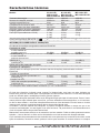 66
66
-
 67
67
-
 68
68
-
 69
69
-
 70
70
-
 71
71
-
 72
72
-
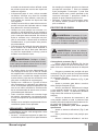 73
73
-
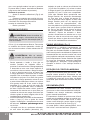 74
74
-
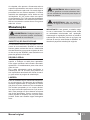 75
75
-
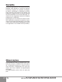 76
76
-
 77
77
-
 78
78
-
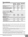 79
79
-
 80
80
-
 81
81
-
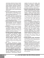 82
82
-
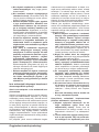 83
83
-
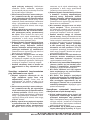 84
84
-
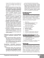 85
85
-
 86
86
-
 87
87
-
 88
88
-
 89
89
-
 90
90
-
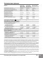 91
91
-
 92
92
-
 93
93
-
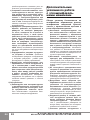 94
94
-
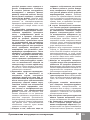 95
95
-
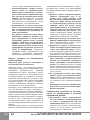 96
96
-
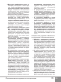 97
97
-
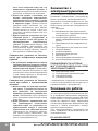 98
98
-
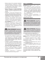 99
99
-
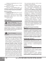 100
100
-
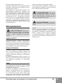 101
101
-
 102
102
-
 103
103
-
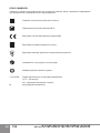 104
104
-
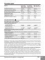 105
105
-
 106
106
-
 107
107
-
 108
108
-
 109
109
-
 110
110
-
 111
111
-
 112
112
-
 113
113
-
 114
114
-
 115
115
-
 116
116
-
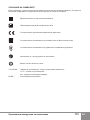 117
117
-
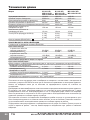 118
118
-
 119
119
-
 120
120
-
 121
121
-
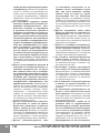 122
122
-
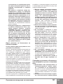 123
123
-
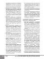 124
124
-
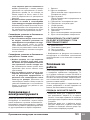 125
125
-
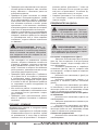 126
126
-
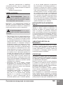 127
127
-
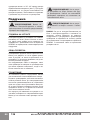 128
128
-
 129
129
-
 130
130


Sparky MB 1600C HD Manual do usuário
- Categoria
- Ferramentas elétricas
- Tipo
- Manual do usuário
- Este manual também é adequado para
em outras línguas
- español: Sparky MB 1600C HD Manual de usuario
- français: Sparky MB 1600C HD Manuel utilisateur
- italiano: Sparky MB 1600C HD Manuale utente
- polski: Sparky MB 1600C HD Instrukcja obsługi
Artigos relacionados
-
Sparky FB 514P Manual do usuário
-
-
-
Sparky Group PMB 2430E Manual do usuário
-
-
-
-
-
-
