Dometic Tank Monitor DTM01P Guia de instalação
- Tipo
- Guia de instalação

DTM01P
Tank monitor
Installation Manual. . . . . . . . . . . . . . . . . . . . . 6
Tankmonitor
Montageanleitung. . . . . . . . . . . . . . . . . . . . 12
Dispositif de surveillance du
réservoir
Instructions de montage . . . . . . . . . . . . . . . 19
Monitor de depósitos
Instrucciones de montaje . . . . . . . . . . . . . .26
Monitor de depósito
Instruções de montagem . . . . . . . . . . . . . .34
Monitor per serbatoi
Indicazioni di montaggio . . . . . . . . . . . . . . 41
Tankmonitor
Montagehandleiding . . . . . . . . . . . . . . . . .48
Tankmonitor
Monteringsvejledning. . . . . . . . . . . . . . . . .54
Tankmätare
Monteringsanvisning. . . . . . . . . . . . . . . . . .60
Tankmonitor
Monteringsanvisning. . . . . . . . . . . . . . . . . .66
Säiliömonitori
Asennusohje . . . . . . . . . . . . . . . . . . . . . . . . 72
Монитор резервуаров
Инструкция по монтажу. . . . . . . . . . . . . . . 78
Monitor zbiornika
Instrukcja montażu . . . . . . . . . . . . . . . . . . . 85
Monitor nádrže
Návod na montáž . . . . . . . . . . . . . . . . . . . . 92
Monitor obsahu nádrže
Návod k montáži . . . . . . . . . . . . . . . . . . . . . 99
Tartályfigyelő berendezés
Szerelési útmutató . . . . . . . . . . . . . . . . . . 105
EN
DE
FR
ES
PT
IT
NL
DA
SV
NO
FI
RU
PL
SK
CS
HU
SANITATION
DTM
DTM01P-M-16s.book Seite 1 Dienstag, 6. September 2016 5:51 17

DTM01P-M-16s.book Seite 2 Dienstag, 6. September 2016 5:51 17

DTM01P
3
1
Full Tank
1
2
3
4
5
2
3
+24 Vg
+12 Vg
ws
bl
rt
sw
ws
5 A
5 A
1
2
DTM01P-M-16s.book Seite 3 Dienstag, 6. September 2016 5:51 17

DTM01P
4
4
Full Tank
32 mm
21 3 4
5
5
6
Full Tank
83 10
290
DTM01P-M-16s.book Seite 4 Dienstag, 6. September 2016 5:51 17

DTM01P
5
7
64
100
114
8
67
51
35
83
Ø2
Ø32
Ø2
DTM01P-M-16s.book Seite 5 Dienstag, 6. September 2016 5:51 17

EN
Explanation of symbols DTM01P
6
Please read this instruction manual carefully before installation and first
use, and store it in a safe place. If you pass on the product to another
person, hand over this instruction manual along with it.
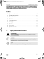
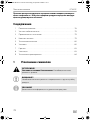
Contents
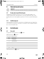
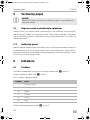
1 Explanation of symbols. . . . . . . . . . . . . . . . . . . . . . . . . . . . . . . . . . . . . . . . . . .6
2 Safety instructions . . . . . . . . . . . . . . . . . . . . . . . . . . . . . . . . . . . . . . . . . . . . . . .7
3 Intended use . . . . . . . . . . . . . . . . . . . . . . . . . . . . . . . . . . . . . . . . . . . . . . . . . . .7
4 Scope of delivery . . . . . . . . . . . . . . . . . . . . . . . . . . . . . . . . . . . . . . . . . . . . . . .7
5 Technical description . . . . . . . . . . . . . . . . . . . . . . . . . . . . . . . . . . . . . . . . . . . .8
6 Installation . . . . . . . . . . . . . . . . . . . . . . . . . . . . . . . . . . . . . . . . . . . . . . . . . . . . .8
7 Warranty . . . . . . . . . . . . . . . . . . . . . . . . . . . . . . . . . . . . . . . . . . . . . . . . . . . . . 11
8 Disposal . . . . . . . . . . . . . . . . . . . . . . . . . . . . . . . . . . . . . . . . . . . . . . . . . . . . . . 11
9 Technical data . . . . . . . . . . . . . . . . . . . . . . . . . . . . . . . . . . . . . . . . . . . . . . . . . 11
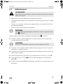
1 Explanation of symbols
!
A
I
CAUTION!
Safety instruction: Failure to observe this instruction can lead to injury.
NOTICE!
Failure to observe this instruction can cause material damage and impair
the function of the product.
NOTE
Supplementary information for operating the product.
DTM01P-M-16s.book Seite 6 Dienstag, 6. September 2016 5:51 17

EN
DTM01P Safety instructions
7
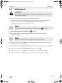
2 Safety instructions
The manufacturer accepts no liability for damage in the following cases:
•Damage to the product resulting from mechanical influences and excess voltage
•Alterations to the product without express permission from the manufacturer
•Use for purposes other than those described in the operating manual
3 Intended use
DTM01P Tank Monitor panel indicates when a wastewater holding tank is almost full.
This monitor helps prevent damage to the boat that can happen because of
accidental overfilling of the holding tank.
A
4Scope of delivery
NOTICE!
Do not use in fuel tank.
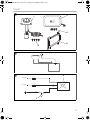
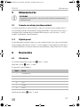
Item in
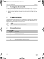
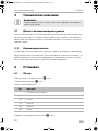
fig. 1, page 3 Description
1 Probe assembly with float switch
2 #8 fasteners for probe assembly
3 Indicator panel
4 #6 fasteners (3.5 mm) for indicator panel
5 Mounting frame for indicator panel
DTM01P-M-16s.book Seite 7 Dienstag, 6. September 2016 5:51 17

EN
Technical description DTM01P
8
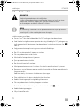
5 Technical description
A
5.1 Probe assembly with float switch
The probe assembly installs into a 32 mm diameter opening on the top of a Dometic
holding tank or other holding tank. As the level of holding tank contents rises, the
float switch inside the tank is pushed upward and activates the “Full Tank” light on
the indicator panel.
5.2 Indicator panel
The indicator panel has a single light which is activated by the float switch inside the
holding tank. When the “Full Tank” light is activated, the operation of any plumbing
fixture connected to the holding tank should stop until the tank is emptied.
6 Installation
6.1 Overview
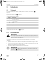
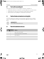
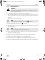
For general installation layout see fig. 2, page 3.
Wiring diagram: fig. 3, page 3.
Key to Wiring diagram
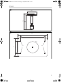
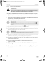
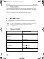
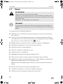
Indicator panel template: fig. 8, page 5.
NOTICE!
Operator must know local regulations for emptying a holding tank.
Item Description
1 Float switch
2 Indicator panel
bl Blue
rt Red
sw Black
ws White
DTM01P-M-16s.book Seite 8 Dienstag, 6. September 2016 5:51 17

EN
DTM01P Installation
9
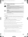
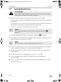
6.2 Indicator panel
!
When selecting the installation location observe the following information:
•Select panel location away from direct contact with water and oil.
•Confirm clearance of 50 mm for wire connections behind wall, hull liner or bulk-
head.
•Make sure the electrical power is shut off.
I
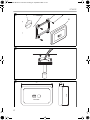
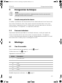
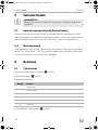
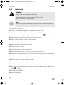
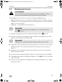
Install the indicator panel as follows (fig. 4, page 4):
➤Using indicator panel template, cut out panel access hole (1) and drill fastener
holes (2).
I
➤Route 1 mm2 stranded copper wire from power source, through 0.5 A fuse (not
provided), to panel location.
➤Route 1 mm2 stranded copper wire from holding tank probe assembly to panel
location.
➤Install mounting frame (3) with four #6 (3.5 mm) fasteners (4).
➤Make proper 12 Vg or 24 Vg wiring connections to indicator panel (5).
➤Push indicator panel (5) onto mounting frame (3) until it locks into place.
CAUTION!
Do not install indicator panel in an atmosphere with potentially flam-
mable or explosive vapors.
NOTE
For electrical connections refer to wiring diagram (fig. 3, page 3).
NOTE
Make sure wires extend out through access hole (1).
DTM01P-M-16s.book Seite 9 Dienstag, 6. September 2016 5:51 17

EN
Installation DTM01P
10
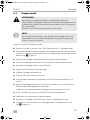
6.3 Probe assembly
!
I
Install the probe as follows:
➤Route 1 mm2 stranded copper wire from DC ground source to probe assembly.
➤Using quick-disconnect terminals, make proper wiring connections from DC
ground source and indicator panel to probe assembly wires (refer to wiring
diagram: fig. 3, page 3).
➤Select probe assembly location away from other tank fittings.
➤Drill 32 mm diameter hole in top of tank.
➤Place probe assembly into center of hole.
➤Mark four fastener locations at corners.
➤Remove probe assembly from hole.
➤Drill fastener holes with 3 mm drill bit.
➤With probe assembly removed from tank, turn on electrical power to system.
➤Move black float up and down to assure proper operation of float and indicator
light.
Red indicator light should illuminate when float is pushed up.
➤After successful test turn off electrical power.
➤Disconnect wires at quick-connect terminals.
➤Place probe assembly into hole in top of holding tank.
➤Use four #8 fasteners (4 mm) to secure probe assembly into holding tank (fig. 5,
page 4).
➤Re-connect wires.
➤Turn on electrical power.
CAUTION!
Do not use probe assembly in fuel tank.
Never install the probe assembly with float switch in tank that contains
anything other than wastewater, gray water or fresh water.
Make sure the electrical power is shut off.
NOTE
For installation in sailboats: Locate probe assembly on athwartships
centerline of tank to assure accuracy when heeled.
DTM01P-M-16s.book Seite 10 Dienstag, 6. September 2016 5:51 17

EN
DTM01P Warranty
11
7Warranty
The statutory warranty period applies. If the product is defective, please contact your
retailer or the manufacturer's branch in your country (see the back of the instruction
manual for the addresses).
For repair and guarantee processing, please include the following documents when
you send in the device:
•A copy of the receipt with purchasing date
•A reason for the claim or description of the fault
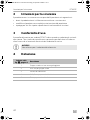
8Disposal
➤Place the packaging material in the appropriate recycling waste bins wherever
possible.
MIf you wish to finally dispose of the product, ask your local recycling centre
or specialist dealer for details about how to do this in accordance with the
applicable disposal regulations.
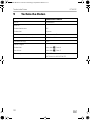
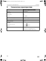
9 Technical data
Tank Monitor DTM01P
Ref. no.: 9108688891
Material
Panel frame: ABS
Panel: Polyester
Float switch: Nitrile rubber ebonite
Average current consumption: 0.016 A at 12 Vg
Fuse: 0.5 A
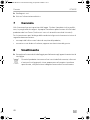
Dimensions
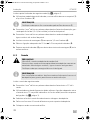
Indicator panel: see fig. 6, page 4
Probe: see fig. 7, page 5
Approvals: ISO8846
EMC Directive 2004/108/EC
DTM01P-M-16s.book Seite 11 Dienstag, 6. September 2016 5:51 17

DE
Erklärung der Symbole DTM01P
12
Bitte lesen Sie diese Anleitung vor Einbau und Inbetriebnahme sorgfältig
durch und bewahren Sie sie auf. Geben Sie sie im Falle einer Weitergabe
des Produktes an den Nutzer weiter.
Inhalt
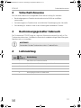
1 Erklärung der Symbole . . . . . . . . . . . . . . . . . . . . . . . . . . . . . . . . . . . . . . . . . .12
2 Sicherheitshinweise . . . . . . . . . . . . . . . . . . . . . . . . . . . . . . . . . . . . . . . . . . . .13
3 Bestimmungsgemäßer Gebrauch . . . . . . . . . . . . . . . . . . . . . . . . . . . . . . . . .13
4 Lieferumfang . . . . . . . . . . . . . . . . . . . . . . . . . . . . . . . . . . . . . . . . . . . . . . . . . .13
5 Technische Beschreibung . . . . . . . . . . . . . . . . . . . . . . . . . . . . . . . . . . . . . . .14
6 Montage . . . . . . . . . . . . . . . . . . . . . . . . . . . . . . . . . . . . . . . . . . . . . . . . . . . . .14
7 Gewährleistung. . . . . . . . . . . . . . . . . . . . . . . . . . . . . . . . . . . . . . . . . . . . . . . .17
8 Entsorgung . . . . . . . . . . . . . . . . . . . . . . . . . . . . . . . . . . . . . . . . . . . . . . . . . . .17
9 Technische Daten . . . . . . . . . . . . . . . . . . . . . . . . . . . . . . . . . . . . . . . . . . . . . .18
1 Erklärung der Symbole
!
A
I
VORSICHT!
Sicherheitshinweis: Nichtbeachtung kann zu Verletzungen führen.
ACHTUNG!
Nichtbeachtung kann zu Materialschäden führen und die Funktion des
Produktes beeinträchtigen.
HINWEIS
Ergänzende Informationen zur Bedienung des Produktes.
DTM01P-M-16s.book Seite 12 Dienstag, 6. September 2016 5:51 17

DE
DTM01P Sicherheitshinweise
13
2 Sicherheitshinweise
Der Hersteller übernimmt in folgenden Fällen keine Haftung für Schäden:
•Beschädigungen am Produkt durch mechanische Einflüsse und Über-
spannungen
•Veränderungen am Produkt ohne ausdrückliche Genehmigung vom Hersteller
•Verwendung für andere als die in der Anleitung beschriebenen Zwecke
3 Bestimmungsgemäßer Gebrauch
Der Tankmonitor DTM01P zeigt an, wenn ein Schmutzwassertank fast voll ist. Der
Tankmonitor dient dazu, Schäden am Boot durch unbeabsichtigte Überfüllung des
Speichertanks zu vermeiden.
A
4 Lieferumfang
ACHTUNG!
Verwenden Sie den Tankmonitor nicht in Treibstofftanks.
Nr. in
Abb. 1, Seite 3 Beschreibung
1 Messfühler mit Schwimmschalter
2 4 mm Schrauben für die Montage des Messfühlers
3 Bedienfeld
4 3,5 mm Schrauben für Bedienfeld
5 Befestigungsrahmen für Bedienfeld
DTM01P-M-16s.book Seite 13 Dienstag, 6. September 2016 5:51 17

DE
Technische Beschreibung DTM01P
14
5 Technische Beschreibung
A
5.1 Montage des Messfühlers mit Schwimmschalter
Der Messfühler wird in einer Öffnung von 32 mm oben auf dem Dometic-
Schmutzwassertank befestigt. Mit steigendem Füllstand des Schmutzwassertanks
wird der Schwimmschalter im Tank nach oben geschoben, wo er die Statusleuchte
„Tank voll“ am Bedienfeld aktiviert.
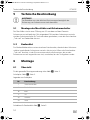
5.2 Bedienfeld
Das Bedienfeld besteht aus einer einzelnen Statusleuchte, die durch den Schwimm-
schalter innerhalb des Schmutzwassertanks aktiviert wird. Wenn die Statusleuchte
„Tank voll“ leuchtet, ist der Wasserzustrom durch alle Armaturen, die an den
Schmutzwassertank angeschlossen sind, anzuhalten, bis der Tank geleert wurde.
6Montage
6.1 Übersicht
Für die generelle Montageanordnung siehe Abb. 2, Seite 3.
Schaltplan: Abb. 3, Seite 3.
Legende zum Schaltplan
Schablone für Bedienfeld: Abb. 8, Seite 5.
ACHTUNG!
Der Betreiber muss die örtlichen Bestimmungen bezüglich der
Entleerung von Schmutzwassertanks beachten.
Nr. Beschreibung
1 Schwimmschalter
2Bedienfeld
bl blau
rt rot
sw schwarz
ws weiß
DTM01P-M-16s.book Seite 14 Dienstag, 6. September 2016 5:51 17

DE
DTM01P Montage
15
6.2 Bedienfeld
!
Beachten Sie bei der Wahl des Montageortes folgende Hinweise:
•Wählen Sie den Standort für das Bedienfeld so, dass direkter Kontakt mit Wasser
oder Öl ausgeschlossen ist.
•Stellen Sie sicher, dass für die erforderlichen Kabelverbindungen hinter Wand,
Verkleidung oder Schott 50 mm frei bleiben.
•Stellen Sie sicher, dass die Spannung abgeschaltet ist.
I
Montieren Sie das Bedienfeld wie folgt (Abb. 4, Seite 4):
➤Verwenden Sie die Schablone des Bedienfelds, um das Loch (1) für das Bedien-
feld und die Befestigungslöcher (2) zu bohren.
I
➤Legen Sie eine Kupferleitung mit einem Querschnitt von 1 mm2 und einer 0,5 A-
Sicherung (nicht im Lieferumfang enthalten) von der Stromquelle zum Einbauort
des Bedienfelds.
➤Legen Sie eine Kupferleitung mit einem Querschnitt von 1 mm2 vom Messfühler
des Schmutzwassertanks zum Bedienfeld.
➤Befestigen Sie den Montagerahmen (3) mit vier Schrauben 3,5 mm (4).
➤Stellen Sie korrekte 12-Vg- oder 24-Vg-Verbindungen zum Bedienfeld (5) her.
➤Drücken Sie das Bedienfeld (5) auf den Befestigungsrahmen (3), bis er einrastet.
VORSICHT!
Installieren Sie das Bedienfeld nicht in Umgebungen mit entzündlichen
oder explosionsfähigen Luftgemischen.
HINWEIS
Die elektrischen Anschlüsse entnehmen Sie bitte dem Schaltplan
(Abb. 3, Seite 3).
HINWEIS
Längen Sie die Kabel so ab, dass ihre Enden aus dem Loch für das
Bedienfeld herausragen (1).
DTM01P-M-16s.book Seite 15 Dienstag, 6. September 2016 5:51 17

DE
Montage DTM01P
16
6.3 Montage des Messfühlers
!
I
Montieren Sie den Messfühler wie folgt:
➤Legen Sie eine Kupferleitung mit einem Querschnitt von 1 mm2 von Masse zum
Messfühler.
➤Verwenden Sie Steckverbinder, um korrekte Stromverbindungen von Masse
und vom Bedienfeld zu den Messfühlerleitungen herzustellen (siehe Schaltplan:
Abb. 3, Seite 3).
➤Wählen Sie den Einbauort für den Messfühler so, dass er sich in einiger
Entfernung von anderen Tankarmaturen befindet.
➤Bohren Sie in den Tankdeckel ein Loch von 32 mm Durchmesser.
➤Stecken Sie den Messfühler mittig in das Loch.
➤Markieren Sie an den Ecken die vier Stellen für die Befestigungsschrauben.
➤Nehmen Sie den Messfühler wieder aus dem Loch.
➤Bohren Sie die Löcher für die Befestigungsschrauben mit einem 3 mm-Bohrer.
➤Schalten Sie den Strom des Systems bei entnommenem Messfühler an.
➤Bewegen Sie den schwarzen Schwimmer auf und nieder, um die korrekte
Funktion des Schwimmers und der Statusleuchte zu prüfen.
Wenn der Schwimmer aufwärts bewegt wird, sollte die Statusleuchte rot
leuchten.
➤Schalten Sie den Strom nach erfolgreicher Prüfung wieder aus.
➤Trennen Sie die Kabel an den Steckverbindern.
➤Stecken Sie den Messfühler in das Loch auf dem Schmutzwassertank.
VORSICHT!
Verwenden Sie den Messfühler nicht in Treibstofftanks.
Installieren Sie den Messfühler mit Schwimmschalter niemals in Tanks,
die andere Inhaltsstoffe als Schmutzwasser, Grauwasser oder Klar-
wasser enthalten.
Stellen Sie sicher, dass die Spannung abgeschaltet ist.
HINWEIS
Bei Installation auf Segelbooten: Befestigen Sie den Messfühler quer zur
Tankmittellinie, um auch bei Seitenneigung des Boots eine korrekte
Anzeige zu erhalten.
DTM01P-M-16s.book Seite 16 Dienstag, 6. September 2016 5:51 17

DE
DTM01P Gewährleistung
17
➤Befestigen Sie den Messfühler mit vier Schrauben 4 mm am Schmutzwassertank
(Abb. 5, Seite 4).
➤Schließen Sie die Kabel erneut an.
➤Schalten Sie die Stromversorgung ein.
7Gewährleistung
Es gilt die gesetzliche Gewährleistungsfrist. Sollte das Produkt defekt sein, wenden
Sie sich bitte an Ihren Fachhändler oder an die Niederlassung des Herstellers in
Ihrem Land (Adressen siehe Rückseite der Anleitung).
Zur Reparatur- bzw. Gewährleistungsbearbeitung müssen Sie folgende Unterlagen
mitschicken:
•eine Kopie der Rechnung mit Kaufdatum,
•einen Reklamationsgrund oder eine Fehlerbeschreibung.
8Entsorgung
➤Geben Sie das Verpackungsmaterial möglichst in den entsprechenden
Recycling-Müll.
MWenn Sie das Produkt endgültig außer Betrieb nehmen, informieren Sie
sich bitte beim nächsten Recyclingcenter oder bei Ihrem Fachhändler
über die zutreffenden Entsorgungsvorschriften.
DTM01P-M-16s.book Seite 17 Dienstag, 6. September 2016 5:51 17

DE
Technische Daten DTM01P
18
9 Technische Daten
Tankmonitor DTM01P
Art.Nr.: 9108688891
Material
Bedienfeldrahmen: ABS
Bedienfeld: Polyester
Schwimmschalter: Nitrilkautschuk-Ebonit
Durchschnittliche Stromaufnahme: 0,016 A bei 12 Vg
Gerätesicherung: 0,5 A
Abmessungen
Bedienfeld: siehe Abb. 6, Seite 4
Messfühler: siehe Abb. 7, Seite 5
Zulassungen: ISO8846
EMC-Richtlinie 2004/108/EC
DTM01P-M-16s.book Seite 18 Dienstag, 6. September 2016 5:51 17

FR
DTM01P Signification des symboles
19
Veuillez lire attentivement cette notice avant le montage et la mise en
service. Veuillez ensuite la conserver. En cas de passer le produit, veuillez
le transmettre au nouvel acquéreur.
Sommaire
1 Signification des symboles . . . . . . . . . . . . . . . . . . . . . . . . . . . . . . . . . . . . . . .19
2 Consignes de sécurité . . . . . . . . . . . . . . . . . . . . . . . . . . . . . . . . . . . . . . . . . 20
3 Usage conforme . . . . . . . . . . . . . . . . . . . . . . . . . . . . . . . . . . . . . . . . . . . . . . 20
4 Pièces fournies . . . . . . . . . . . . . . . . . . . . . . . . . . . . . . . . . . . . . . . . . . . . . . . 20
5 Désignation technique . . . . . . . . . . . . . . . . . . . . . . . . . . . . . . . . . . . . . . . . . .21
6 Montage . . . . . . . . . . . . . . . . . . . . . . . . . . . . . . . . . . . . . . . . . . . . . . . . . . . . .21
7 Garantie. . . . . . . . . . . . . . . . . . . . . . . . . . . . . . . . . . . . . . . . . . . . . . . . . . . . . 24
8 Retraitement . . . . . . . . . . . . . . . . . . . . . . . . . . . . . . . . . . . . . . . . . . . . . . . . . 24
9 Caractéristiques techniques. . . . . . . . . . . . . . . . . . . . . . . . . . . . . . . . . . . . . 25
1 Signification des symboles
!
A
I
ATTENTION !
Consigne de sécurité : le non-respect de ces consignes peut entraîner
des blessures.
AVIS !
Le non-respect de ces consignes peut entraîner des dommages maté-
riels et des dysfonctionnements du produit.
REMARQUE
Informations complémentaires sur l'utilisation du produit.
DTM01P-M-16s.book Seite 19 Dienstag, 6. September 2016 5:51 17

FR
Consignes de sécurité DTM01P
20
2 Consignes de sécurité
Le fabricant décline toute responsabilité pour des dommages dans les cas suivants :
•des influences mécaniques et des surtensions ayant endommagé le matériel
•des modifications apportées au produit sans autorisation explicite de la part du
fabricant
•une utilisation différente de celle décrite dans la notice
3Usage conforme
Le panneau du moniteur de cuve DTM01P indique lorsqu'une cuve à eaux noires est
presque pleine. Ce moniteur permet d'éviter d'endommager le bateau en cas de
débordement accidentel de la cuve à eaux noires.
A
4Pièces fournies
AVIS !
Ne pas utiliser dans une cuve de carburant.
Article en fig. 1,
page 3 Description
1 Sonde avec poire de niveau
2 Dispositifs de fixation 4 mm pour sonde
3 Panneau indicateur
4 Dispositifs de fixation 3,5 mm pour panneau indicateur
5 Cadre de montage pour panneau indicateur
DTM01P-M-16s.book Seite 20 Dienstag, 6. September 2016 5:51 17
A página está carregando...
A página está carregando...
A página está carregando...
A página está carregando...
A página está carregando...
A página está carregando...
A página está carregando...
A página está carregando...
A página está carregando...
A página está carregando...
A página está carregando...
A página está carregando...
A página está carregando...
A página está carregando...
A página está carregando...
A página está carregando...
A página está carregando...
A página está carregando...
A página está carregando...
A página está carregando...
A página está carregando...
A página está carregando...
A página está carregando...
A página está carregando...
A página está carregando...
A página está carregando...
A página está carregando...
A página está carregando...
A página está carregando...
A página está carregando...
A página está carregando...
A página está carregando...
A página está carregando...
A página está carregando...
A página está carregando...
A página está carregando...
A página está carregando...
A página está carregando...
A página está carregando...
A página está carregando...
A página está carregando...
A página está carregando...
A página está carregando...
A página está carregando...
A página está carregando...
A página está carregando...
A página está carregando...
A página está carregando...
A página está carregando...
A página está carregando...
A página está carregando...
A página está carregando...
A página está carregando...
A página está carregando...
A página está carregando...
A página está carregando...
A página está carregando...
A página está carregando...
A página está carregando...
A página está carregando...
A página está carregando...
A página está carregando...
A página está carregando...
A página está carregando...
A página está carregando...
A página está carregando...
A página está carregando...
A página está carregando...
A página está carregando...
A página está carregando...
A página está carregando...
A página está carregando...
A página está carregando...
A página está carregando...
A página está carregando...
A página está carregando...
A página está carregando...
A página está carregando...
A página está carregando...
A página está carregando...
A página está carregando...
A página está carregando...
A página está carregando...
A página está carregando...
A página está carregando...
A página está carregando...
A página está carregando...
A página está carregando...
A página está carregando...
A página está carregando...
A página está carregando...
A página está carregando...
-
 1
1
-
 2
2
-
 3
3
-
 4
4
-
 5
5
-
 6
6
-
 7
7
-
 8
8
-
 9
9
-
 10
10
-
 11
11
-
 12
12
-
 13
13
-
 14
14
-
 15
15
-
 16
16
-
 17
17
-
 18
18
-
 19
19
-
 20
20
-
 21
21
-
 22
22
-
 23
23
-
 24
24
-
 25
25
-
 26
26
-
 27
27
-
 28
28
-
 29
29
-
 30
30
-
 31
31
-
 32
32
-
 33
33
-
 34
34
-
 35
35
-
 36
36
-
 37
37
-
 38
38
-
 39
39
-
 40
40
-
 41
41
-
 42
42
-
 43
43
-
 44
44
-
 45
45
-
 46
46
-
 47
47
-
 48
48
-
 49
49
-
 50
50
-
 51
51
-
 52
52
-
 53
53
-
 54
54
-
 55
55
-
 56
56
-
 57
57
-
 58
58
-
 59
59
-
 60
60
-
 61
61
-
 62
62
-
 63
63
-
 64
64
-
 65
65
-
 66
66
-
 67
67
-
 68
68
-
 69
69
-
 70
70
-
 71
71
-
 72
72
-
 73
73
-
 74
74
-
 75
75
-
 76
76
-
 77
77
-
 78
78
-
 79
79
-
 80
80
-
 81
81
-
 82
82
-
 83
83
-
 84
84
-
 85
85
-
 86
86
-
 87
87
-
 88
88
-
 89
89
-
 90
90
-
 91
91
-
 92
92
-
 93
93
-
 94
94
-
 95
95
-
 96
96
-
 97
97
-
 98
98
-
 99
99
-
 100
100
-
 101
101
-
 102
102
-
 103
103
-
 104
104
-
 105
105
-
 106
106
-
 107
107
-
 108
108
-
 109
109
-
 110
110
-
 111
111
-
 112
112


Dometic Tank Monitor DTM01P Guia de instalação
- Tipo
- Guia de instalação
em outras línguas
Artigos relacionados
-
Dometic PerfectRoof PR4500 Guia de instalação
-
Dometic PerfectRoof PR4500 Guia de instalação
-
-
-
-
-
-
Dometic SP950C, SPX1200C Fastening frame for DAF Space Cab/Super Space Cab Guia de instalação
-