Bosch GHO 185-LI Manual do usuário
- Categoria
- Plainas de energia
- Tipo
- Manual do usuário

Robert Bosch Power Tools GmbH
70538 Stuttgart
GERMANY
www.bosch-pt.com
1 609 92A 8GP (2023.06) O / 103
en Original instructions
fr Notice originale
pt Manual original
es Manual original
pt Manual de instruções original
zh 正本使用明
zh 原始使用說明書
th
id Petunjuk-Petunjuk untuk
Penggunaan Orisinal
vi Bn gc hng dn s dng
ar
fa
1 609 92A 8GP
GHO 185-LI Professional

2 |
English ...................................................Page 8
Français..................................................Page 15
Português .............................................. Página 23
Español ................................................ Página 32
Português do Brasil..................................... Página 40
....................................................... 48
.................................................. 54
...................................................... 61
Bahasa Indonesia..................................... Halaman 68
Ting Vit............................................... Trang 76
.................................................. 85
.................................................. 93
1 609 92A 8GP | (01.06.2023) Bosch Power Tools

| 3
HSS
HSS
B
A
(1)
(1)
(2)
(3)
(3)
(4)
(5)
(6) (7)
(10)
(11)
(2)
(36)
(13)
(11)
(14)
(15)
(19)(20)(18)(17)(16)
(12)
(38)
Bosch Power Tools 1 609 92A 8GP | (01.06.2023)

4 |
HSS
HSS
23 mm
min.
6 mm max. HSS
HSS
TC
TC
G
H
C
D
E
F
(23)
(20) (19) (18)
(21)
(13) (20)
(19)
(18)
(13) (14)
(13)
(14)
(15)
(11)
(16)
(22)
1 609 92A 8GP | (01.06.2023) Bosch Power Tools

| 5
TC
TC
TC
82 mm
max
9 mm
max
J
K
I
L
M
(23)
(13)
(14) (24)
(27)
(26)
(25)
(30) (31)
Bosch Power Tools 1 609 92A 8GP | (01.06.2023)

6 |
Ø 35 mm
45°
Q
R
P
O
N
(28)
(29)
(3)
(10)
(11)
(32)
(12)
(33)
(9) (8)
(35)
(34)
(33)
1 609 92A 8GP | (01.06.2023) Bosch Power Tools

| 7
TC
S
(13) (20)
(19)
(37)
(22)
(37)
(23)
Bosch Power Tools 1 609 92A 8GP | (01.06.2023)

8 | English
English
Safety Instructions
General Power Tool Safety Warnings
WARNING Read all safety warnings, instruc-
tions, illustrations and specifica-
tions provided with this power tool. Failure to follow all in-
structions listed below may result in electric shock, fire and/
or serious injury.
Save all warnings and instructions for future reference.
The term "power tool" in the warnings refers to your mains-
operated (corded) power tool or battery-operated (cord-
less) power tool.
Work area safety
uKeep work area clean and well lit. Cluttered or dark
areas invite accidents.
uDo not operate power tools in explosive atmospheres,
such as in the presence of flammable liquids, gases or
dust. Power tools create sparks which may ignite the dust
or fumes.
uKeep children and bystanders away while operating a
power tool. Distractions can cause you to lose control.
Electrical safety
uPower tool plugs must match the outlet. Never modify
the plug in any way. Do not use any adapter plugs with
earthed (grounded) power tools. Unmodified plugs and
matching outlets will reduce risk of electric shock.
uAvoid body contact with earthed or grounded sur-
faces, such as pipes, radiators, ranges and refrigerat-
ors. There is an increased risk of electric shock if your
body is earthed or grounded.
uDo not expose power tools to rain or wet conditions.
Water entering a power tool will increase the risk of elec-
tric shock.
uDo not abuse the cord. Never use the cord for carry-
ing, pulling or unplugging the power tool. Keep cord
away from heat, oil, sharp edges or moving parts.
Damaged or entangled cords increase the risk of electric
shock.
uWhen operating a power tool outdoors, use an exten-
sion cord suitable for outdoor use. Use of a cord suit-
able for outdoor use reduces the risk of electric shock.
uIf operating a power tool in a damp location is un-
avoidable, use a residual current device (RCD) protec-
ted supply. Use of an RCD reduces the risk of electric
shock.
Personal safety
uStay alert, watch what you are doing and use common
sense when operating a power tool. Do not use a
power tool while you are tired or under the influence
of drugs, alcohol or medication. A moment of inatten-
tion while operating power tools may result in serious per-
sonal injury.
uUse personal protective equipment. Always wear eye
protection. Protective equipment such as a dust mask,
non-skid safety shoes, hard hat or hearing protection
used for appropriate conditions will reduce personal in-
juries.
uPrevent unintentional starting. Ensure the switch is in
the off-position before connecting to power source
and/or battery pack, picking up or carrying the tool.
Carrying power tools with your finger on the switch or en-
ergising power tools that have the switch on invites acci-
dents.
uRemove any adjusting key or wrench before turning
the power tool on. A wrench or a key left attached to a
rotating part of the power tool may result in personal in-
jury.
uDo not overreach. Keep proper footing and balance at
all times. This enables better control of the power tool in
unexpected situations.
uDress properly. Do not wear loose clothing or jew-
ellery. Keep your hair and clothing away from moving
parts. Loose clothes, jewellery or long hair can be caught
in moving parts.
uIf devices are provided for the connection of dust ex-
traction and collection facilities, ensure these are con-
nected and properly used. Use of dust collection can re-
duce dust-related hazards.
uDo not let familiarity gained from frequent use of tools
allow you to become complacent and ignore tool
safety principles. A careless action can cause severe in-
jury within a fraction of a second.
Power tool use and care
uDo not force the power tool. Use the correct power
tool for your application. The correct power tool will do
the job better and safer at the rate for which it was de-
signed.
uDo not use the power tool if the switch does not turn it
on and off. Any power tool that cannot be controlled
with the switch is dangerous and must be repaired.
uDisconnect the plug from the power source and/or re-
move the battery pack, if detachable, from the power
tool before making any adjustments, changing ac-
cessories, or storing power tools. Such preventive
safety measures reduce the risk of starting the power tool
accidentally.
uStore idle power tools out of the reach of children and
do not allow persons unfamiliar with the power tool or
these instructions to operate the power tool. Power
tools are dangerous in the hands of untrained users.
uMaintain power tools and accessories. Check for mis-
alignment or binding of moving parts, breakage of
parts and any other condition that may affect the
power tool’s operation. If damaged, have the power
tool repaired before use. Many accidents are caused by
poorly maintained power tools.
1 609 92A 8GP | (01.06.2023) Bosch Power Tools

English | 9
uKeep cutting tools sharp and clean. Properly main-
tained cutting tools with sharp cutting edges are less
likely to bind and are easier to control.
uUse the power tool, accessories and tool bits etc. in
accordance with these instructions, taking into ac-
count the working conditions and the work to be per-
formed. Use of the power tool for operations different
from those intended could result in a hazardous situation.
uKeep handles and grasping surfaces dry, clean and
free from oil and grease. Slippery handles and grasping
surfaces do not allow for safe handling and control of the
tool in unexpected situations.
Battery tool use and care
uRecharge only with the charger specified by the manu-
facturer. A charger that is suitable for one type of bat-
tery pack may create a risk of fire when used with another
battery pack.
uUse power tools only with specifically designated bat-
tery packs. Use of any other battery packs may create a
risk of injury and fire.
uWhen battery pack is not in use, keep it away from
other metal objects, like paper clips, coins, keys,
nails, screws or other small metal objects, that can
make a connection from one terminal to another.
Shorting the battery terminals together may cause burns
or a fire.
uUnder abusive conditions, liquid may be ejected from
the battery; avoid contact. If contact accidentally oc-
curs, flush with water. If liquid contacts eyes, addi-
tionally seek medical help. Liquid ejected from the bat-
tery may cause irritation or burns.
uDo not use a battery pack or tool that is damaged or
modified. Damaged or modified batteries may exhibit
unpredictable behaviour resulting in fire, explosion or risk
of injury.
uDo not expose a battery pack or tool to fire or excess-
ive temperature. Exposure to fire or temperature above
130°C may cause explosion.
uFollow all charging instructions and do not charge the
battery pack or tool outside the temperature range
specified in the instructions. Charging improperly or at
temperatures outside the specified range may damage
the battery and increase the risk of fire.
Service
uHave your power tool serviced by a qualified repair
person using only identical replacement parts. This
will ensure that the safety of the power tool is maintained.
uNever service damaged battery packs. Service of bat-
tery packs should only be performed by the manufacturer
or authorized service providers.
Safety instructions for planers
uWait for the cutter to stop before setting the tool
down. An exposed rotating cutter may engage the sur-
face leading to possible loss of control and serious injury.
uUse clamps or another practical way to secure and
support the workpiece to a stable platform. Holding
the workpiece by your hand or against the body leaves it
unstable and may lead to loss of control.
uOnly bring the power tool into contact with the work-
piece when switched on. Otherwise there is danger of
kickback if the cutting tool jams in the workpiece.
uDo not allow the chip ejector to come into contact with
your hands. You may be injured by rotating parts.
uNever plane over metal objects, nails or screws. Cut-
ters and cutter shafts could become damaged and cause
increased vibration.
uUse suitable detectors to determine if there are hid-
den supply lines or contact the local utility company
for assistance. Contact with electric cables can cause
fire and electric shock. Damaging gas lines can lead to ex-
plosion. Breaking water pipes causes property damage.
uWhile working, always hold the planer in such a way
that the planer base plate lies flat against the work-
piece. Otherwise the planer could slip and cause injury.
uIn case of damage and improper use of the battery, va-
pours may be emitted. The battery can set alight or ex-
plode. Ensure the area is well ventilated and seek medical
attention should you experience any adverse effects. The
vapours may irritate the respiratory system.
uDo not open the battery. There is a risk of short-circuit-
ing.
uThe battery can be damaged by pointed objects such
as nails or screwdrivers or by force applied externally.
An internal short circuit may occur, causing the battery to
burn, smoke, explode or overheat.
uOnly use the battery with products from the manufac-
turer. This is the only way in which you can protect the
battery against dangerous overload.
Protect the battery against heat, e.g. against
continuous intense sunlight, fire, dirt, water
and moisture. There is a risk of explosion and
short-circuiting.
uHold the power tool firmly with both hands and make
sure you have a stable footing. The power tool can be
more securely guided with both hands.
Product Description and
Specifications
Read all the safety and general instructions.
Failure to observe the safety and general in-
structions may result in electric shock, fire
and/or serious injury.
Please observe the illustrations at the beginning of this oper-
ating manual.
Intended use
The power tool is intended for planing wood-based materials
such as beams and boards while resting firmly on the work-
Bosch Power Tools 1 609 92A 8GP | (01.06.2023)

10 | English
piece. It is also suitable for chamfering edges and for rebat-
ing.
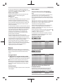
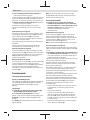
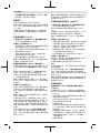
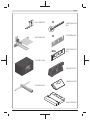
Product features
The numbering of the product features refers to the diagram
of the power tool on the graphics page.
(1) Cutting depth scale
(2) Knob for setting the cutting depth
(insulated gripping surface)
(3) Chip ejector (either right or left)
(4) Lock-off function for On/Off switch
(5) On/off switch
(6) Rechargeable batterya)
(7) Rechargeable battery release buttona)
(8) Screw for belt cover
(9) Belt cover
(10) Changeover lever for chip ejector direction
(11) Planer base plate
(12) V-grooves
(13) T-handle socket spanner/Torx keys
(14) Fastening screw for clamping jaw
(15) Clamping jaw
(16) Blade head
(17) Guide groove for planer blade
(18) HSS planer blade
(19) HSS planer blade retaining clip
(20) Fastening screw for HSS planer blade retaining clip
(21) Sharpening aid for HSS planer blades
(22) Setting gauge for HSS planer blades
(23) HM/TC planer bladea)
(24) Parallel guide
(25) Scale for rebate width
(26) Locking nut for rebate width setting
(27) Fastening screw for parallel guide
(28) Extraction hose (dia.35mm)a)
(29) Chip/dust baga)
(30) Fastening screw for rebate depth guidea)
(31) Rebate depth guidea)
(32) Parking rest
(33) Drive belt
(34) Large belt wheel
(35) Small belt wheel
(36) Handle (insulated gripping surface)
(37) Adapter for converting from HSS to TC planer
bladesa)
(38) Battery charge indicator on the power tool
a) Accessories shown or described are not included with the
product as standard. You can find the complete selection of
accessories in our accessories range.
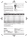
Technical data
Planer GHO 185-LI
Article number 3 601 EB5 0..
Rated voltage V 18
No-load speedA) min–1 14,000
Cutting depth mm 0–2.6
Rebate depth mm 0–9
Max. planing width mm 82
Weight according to EPTA-Pro-
cedure01:2014B) kg 2.6–3.7
Recommended ambient tem-
perature during charging
°C 0to+35
Permitted ambient temperature
during operationC) and during
storage
°C –20to+50
Recommended rechargeable
batteries
GBA18V…
ProCORE18V…
Recommended chargers GAL 18…
GAX 18…
GAL 36…
A) Measured at 20–25°C with rechargeable battery GBA 18V
4.0Ah.
B) Depends on battery in use
C) Limited performance at temperatures <0°C
Values can vary depending upon the product and are subject to ap-
plication and environmental conditions. For further information
www.bosch-professional.com/wac.
Noise/vibration information
Noise emission values determined according to
EN62841-2-14.
Typically, the A-weighted noise level of the power tool is:
Sound pressure level 91dB(A); sound power level
99dB(A). Uncertainty K=3dB.
Wear hearing protection!
Vibration total values ah (triax vector sum) and uncertainty K
determined according to EN62841-2-14:
ah=3.5m/s2, K=1.5m/s2.
The vibration level and noise emission value given in these
instructions have been measured in accordance with a
standardised measuring procedure and may be used to com-
pare power tools. They may also be used for a preliminary
estimation of vibration and noise emissions.
The stated vibration level and noise emission value repres-
ent the main applications of the power tool. However, if the
power tool is used for other applications, with different ac-
cessories or is poorly maintained, the vibration level and
noise emission value may differ. This may significantly in-
crease the vibration and noise emissions over the total work-
ing period.
To estimate vibration and noise emissions accurately, the
times when the tool is switched off or when it is running but
not actually being used should also be taken into account.
1 609 92A 8GP | (01.06.2023) Bosch Power Tools

English | 11
This may significantly reduce vibration and noise emissions
over the total working period.
Implement additional safety measures to protect the oper-
ator from the effects of vibration, such as servicing the
power tool and accessories, keeping their hands warm, and
organising workflows correctly.
Rechargeable battery
Bosch sells some cordless power tools without a re-
chargeable battery. You can tell whether a rechargeable bat-
tery is included with the power tool by looking at the pack-
aging.
Charging the battery
uUse only the chargers listed in the technical data. Only
these chargers are matched to the lithium-ion battery of
your power tool.
Note: Lithium-ion rechargeable batteries are supplied par-
tially charged according to international transport regula-
tions. To ensure full rechargeable battery capacity, fully
charge the rechargeable battery before using your tool for
the first time.
Inserting the Battery
Push the charged battery into the battery holder until it
clicks into place.
Removing the Battery
To remove the rechargeable battery, press the battery re-
lease button and pull the battery out. Do not use force to do
this.
The rechargeablebattery has two locking levels to prevent
the battery from falling out if the battery releasebutton is
pressed unintentionally. The rechargeable battery is held in
place by a spring when fitted in the power tool.
Battery Charge Indicator on the Rechargeable
Battery
Note: Not all battery types have a battery charge indicator.
The green LEDs on the battery charge indicator indicate the
state of charge of the battery. For safety reasons, it is only
possible to check the state of charge when the power tool is
not in operation.
Press the button for the battery charge indicator or to
show the state of charge. This is also possible when the bat-
tery is removed.
If no LED lights up after pressing the button for the battery
charge indicator, then the battery is defective and must be
replaced.
Battery model GBA 18V...
LED Capacity
3× continuous green light 60–100%
LED Capacity
2× continuous green light 30–60%
1× continuous green light 5–30%
1× flashing green light 0–5%
Battery model ProCORE18V...
LED Capacity
5 × continuous green light 80–100%
4 × continuous green light 60–80%
3 × continuous green light 40–60%
2 × continuous green light 20–40%
1 × continuous green light 5–20%
1 × flashing green light 0–5%
Battery Charge Indicator on the Power Tool
The battery charge indicator on the power tool indicates the
remaining battery capacity or an overload when the power
tool is switched on.
LED Capacity
3× continuous green light 60–100%
2× continuous green light 30–60%
1× continuous green light 5–30%
1× flashing green light 0–5%
LED Meaning
Flashing light 3× Overload protection has been triggered
Flashing light
middle LED
The temperature of the rechargeable bat-
tery is outside of the operating temperat-
ure range and/or the power tool's tem-
perature protection has been triggered
Recommendations for Optimal Handling of the
Battery
Protect the battery against moisture and water.
Only store the battery within a temperature range of −20 to
50°C. Do not leave the battery in your car in the summer, for
example.
Occasionally clean the ventilation slots on the battery using a
soft brush that is clean and dry.
A significantly reduced operating time after charging indic-
ates that the battery has deteriorated and must be replaced.
Follow the instructions on correct disposal.
Fitting
uRemove the battery from the power tool before carry-
ing out work on the power tool (e.g. maintenance,
changing tool, etc.). The battery should also be re-
Bosch Power Tools 1 609 92A 8GP | (01.06.2023)

12 | English
moved for transport and storage. There is risk of injury
from unintentionally pressing the on/off switch.
Choosing the Planer Blade
The power tool can be fitted with different planer blades.
Fitting the adapter (37) (accessory) allows the power tool to
be changed from HSS planer blades (18) to HM/TC planer
blades (23).
Always change both planer blades – replacing just one blade
will create an imbalance that could cause vibrations and
shorten the service life of the power tool.
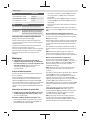
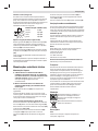
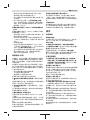
Changing the HSS Planer Blades
uTake care when changing the planer blade. Do not pick
up the planer blade by the cutting edges. You may be
injured by the sharp cutting edges.
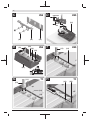
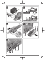
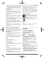
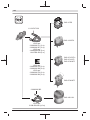
Removing the Planer Blades (see figures A–C)
– To replace the planer blades, turn the blade head (16)
until the clamping jaw (15) is parallel with the planer base
plate (11).
– Unscrew the three fastening screws(14) with the T-
handle socket spanner(13) and remove the clamping
jaw(15).
– Push the retaining clip (19) together with the planer
blade (18) out of the blade head (16) and/or the guide
groove (17).
– Turn the blade head 180° and remove the second planer
blade.
Note: Before changing or resharpening the planer blades,
remove the retaining clip (19) by undoing the fastening
screw (20).
Resharpening HSS Planer Blades (see figure D)
Worn or blunt HSS planer blades can be resharpened using
the sharpening aid (21) (accessory) and a commercially
available grinding stone.
Place both planer blades in the sharpening aid and clamp
them firmly with the wing bolt. Make sure that both planer
blades are pushed in fully.
Move the planer blades placed in the sharpening aid steadily
across the grinding stone, applying light pressure.
Note: The planer blades must not be resharpened by more
than 6mm (i.e. to a minimum width of 23mm). Both planer
blades must be replaced when they reach this size.
Fitting the Planer Blades (see figures E–F)
Before (re)inserting new or resharpened planer blades,
clean the blade head (16) and, if necessary, the planer
blade (18) and the retaining clip (19). Clean heavily
gummed planer blades with spirits or petroleum.
Note: New and resharpened planer blades must always be
set to the correct height before fitting.
The setting gauge (22) (accessory) is used to adjust the
height of the planer blades. Place the planer blade (18) and
the retaining clip (19) on the setting gauge. Make sure that
the blade retainer (19) engages in the groove intended for
this purpose. Press the planer blade (18) against the guide
and fix the retaining clip (19) in this position with the fasten-
ing screw (20). This will automatically adjust the correct
height.
The planer blade must be fitted and aligned with the centre
of the planer base plate(11). Then tighten the three
fastening screws(14) with the T-handle socket
spanner(13). Ensure that the tightening sequence
() on the clamping jaw(15) is followed correctly.
Note: Check that the fastening screws (14) are firmly
tightened before start-up. Turn the blade head (16) by hand
and ensure that the planer blades are not brushing against
anything.
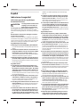
Changing the HM/TC Planer Blades
uTake care when changing the planer blade. Do not pick
up the planer blade by the cutting edges. You may be
injured by the sharp cutting edges.
Use only original Bosch HM/TC planer blades.
Hard metal (HM/TC) planer blades have two cutting edges
and can be turned. If both cutting edges become blunt, the
planer blades (23) need to be changed. HM/TC planer
blades must not be resharpened.
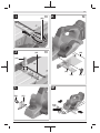
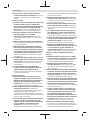
Removing the Planer Blades (see figures G–H)
– To turn or replace the planer blades, turn the blade head
(16) until the clamping jaw (15) is parallel with the planer
base plate (11).
– Undo the three fastening screws (14) using the Torx key
(13) (approx. 1–2 turns). The clamping jaw (15) does
not need to be removed.
– Turn the blade head slightly and use a piece of wood to
push the planer blade (23) to the side and out of the
blade head (16).
– Turn the blade head 180° and remove the second planer
blade.
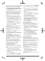
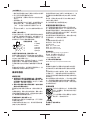
Fitting the Planer Blades (see figures I–J)
The guide groove on the planer blade ensures a constant,
even height setting when changing or turning the blade.
If necessary, clean the blade seat in the blade head (16) and
the planer blade (23).
When fitting the planer blade, ensure that it is correctly
seated in the mounting guide of the blade head (16).
The planer blade must be fitted and aligned with the centre
of the planer base plate (11). Then tighten the three
fastening screws (14) using the Torx key (13), following the
tightening sequence () specified on the clamping jaw
(15).
Note: Check that the fastening screws (14) are firmly
tightened before start-up. Turn the blade head (16) by hand
and ensure that the planer blades are not brushing against
anything.
1 609 92A 8GP | (01.06.2023) Bosch Power Tools

English | 13
Use of conversion kits
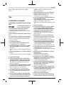
Changing from HSS to HM/TC
The HM/TC adapter enables a planer fitted with HSS planer
blades to be changed over to HM/TC planer blades.
– Unscrew the three fastening screws (14) using the Torx
key (13) and remove the clamping jaw (15).
– Push the retaining clip (19) together with the planer
blade (18) out of the blade head (16) and/or the guide
groove (17).
– Remove the screws (20).
– Place the retaining clip (19) and the adapter (37) in the
setting gauge (22). The retaining clip (19) must slot into
the groove on the setting gauge (see figure S).
– Push the HM/TC planer blade (23) into the adapter (37)
from the side. The ridge on the adapter (37) must slot
into the groove on the HM/TC planer blade (see figure S).
– Tighten the screws (20).
– Insert the retaining clip (19) together with the adapter
(37) and the planer blade (18) into the blade head (16)
and/or the guide groove (17).
– Put the clamping jaw (15) on and insert the fastening
screws (14), which do not yet need to be screwed in
tightly.
– The planer blade must be fitted and aligned with the
centre of the planer base plate (11). Then tighten the
three fastening screws (14) using the Torx key (13), fol-
lowing the tightening sequence () specified on
the clamping jaw (15).
Changing from HM/TC to HSS
Planers fitted with HM/TC planer blades can be changed
over to HSS planer blades.
– Unscrew the three fastening screws (14) using the Torx
key (13) and remove the clamping jaw (15).
– Push the retaining clip (19) together with the planer
blade (18) and/or the HM/TC adapter (37) out of the
blade head (16).
– Remove the screws (20).
– Fit the assembled HSS planer blade (see "Fitting the
Planer Blades (see figures E–F)", page12) and align it
with the centre of the planer base plate (11).
– Put the clamping jaw (15) on and tighten the three
fastening screws (14) using the Torx key (13), following
the tightening sequence () specified on the
clamping jaw (15).
Dust/Chip Extraction
The dust from materials such as lead paint, some types of
wood, minerals and metal can be harmful to human health.
Touching or breathing in this dust can trigger allergic reac-
tions and/or cause respiratory illnesses in the user or in
people in the near vicinity.
Certain dusts, such as oak or beech dust, are classified as
carcinogenic, especially in conjunction with wood treatment
additives (chromate, wood preservative). Materials contain-
ing asbestos may only be machined by specialists.
– Use a dust extraction system that is suitable for the ma-
terial wherever possible.
– Provide good ventilation at the workplace.
– It is advisable to wear a P2 filter class breathing mask.
The regulations on the material being machined that apply in
the country of use must be observed.
uAvoid dust accumulation at the workplace. Dust can
easily ignite.
Clean the chip ejector (3) regularly. Clean a clogged chip
ejector using a suitable tool, e.g. a piece of wood, com-
pressed air, etc.
uDo not allow the chip ejector to come into contact with
your hands. You may be injured by rotating parts.
Always use an external dust extraction device or chip/dust
bag to guarantee optimum suction.
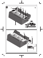
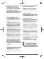
External dust extraction (see figure N)
An extraction hose (dia. 35 mm) (28) (accessory) can be
connected to the chip ejector on either side.
Connect the dust extraction hose (28) to a dust extractor
(accessory). You will find an overview of how to connect to
various dust extractors at the end of these operating instruc-
tions.
The dust extractor must be suitable for the material being
worked.
When extracting dry dust that is especially detrimental to
health or carcinogenic, use a special dust extractor.
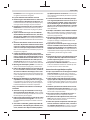
Self-generated dust extraction (see figure N)
A chip/dust bag (accessory) (29) can be used for smaller
jobs. Insert the dust bag nozzle of the chip/dust bag firmly
into the chip ejector (3). Empty the chip/dust bag (29) at
regular intervals to maintain optimum dust collection.
Selectable chip ejector
Using the changeover lever (10), the chip ejector can be (3)
adjusted to the right or left. Push the changeover lever (10)
all the way towards the end position until it clicks into place.
The selected chip ejector direction is indicated by an arrow
symbol on the changeover lever (10).
Operation
Start-up
Setting the cutting depth
Using the knob (2), the cutting depth can be continuously
adjusted between 0–2.6mm with the aid of the cutting
depth scale (1) (scale division=0.1 mm).
Switching on/off
uMake sure that you are able to press the On/Off switch
without releasing the handle.
To start the power tool, first press the lock-off switch(4),
then press and hold the on/off switch(5).
To switch off the power tool, release the on/off switch(5).
Note: For safety reasons, the on/off switch(5) cannot be
locked; it must remain pressed during the entire operation.
Bosch Power Tools 1 609 92A 8GP | (01.06.2023)

14 | English
Practical advice
uRemove the battery from the power tool before carry-
ing out work on the power tool (e.g. maintenance,
changing tool, etc.). The battery should also be re-
moved for transport and storage. There is risk of injury
from unintentionally pressing the on/off switch.
Parking rest (see figure O)
The parking rest (32) makes it possible to put down the
power tool directly after working, without any danger of
damaging the workpiece or planer blade. During the work
process, the parking rest (32) is highly pivoted and the rear
section of the planer base plate (11) is released.
Note: The parking rest (32) must not be removed.
Planing Procedure (see figure O)
Set the required cutting depth and position the power tool
with the front section of the planer base plate (11) on the
workpiece.
uOnly bring the power tool into contact with the work-
piece when switched on. Otherwise there is danger of
kickback if the cutting tool jams in the workpiece.
Switch on the power tool and guide it over the surface of the
workpiece, applying uniform feed.
To achieve high-quality surfaces, apply only a low feed rate
and exert pressure on the middle of the planer base plate.
For the processing of hard materials, such as hardwood, and
also when utilising the maximum planing width, set only a
low cutting depth and reduce the planer feed as appropriate.
Excessive feed reduces the quality of the surface finish and
can lead to the chip ejector quickly becoming blocked.
Only sharp planer blades achieve good cutting performance
and make the power tool last longer.
The integrated parking rest (32) also enables a continuation
of the planing procedure following interruption at any point
on the workpiece:
– Place the power tool – with parking rest folded down –
onto the area of the workpiece that you will continue to
work on.
– Switch the power tool on.
– Shift the contact pressure onto the front of the planer
base plate and slowly slide the power tool forward (). In
doing so, the parking rest will swivel upwards and out of
the way (), meaning that the rear section of the planer
base plate is in contact with the workpiece again.
– Guide the power tool over the surface of the workpiece,
applying uniform feed ().
Chamfering edges (see figure P)
The V-grooves in the front of the planer base plate enable
quick and easy chamfering of workpiece edges. Select the V-
groove that corresponds to your chamfering width. Then po-
sition the planer with the V-groove onto the edge of the
workpiece and guide it along.
Groove used Dimension a
(mm)
None 0–2.5
Small 1.5–4.0
Medium 2.0–4.5
Large 3.0–5.5
Planing with the Parallel Guide (see figures K–M)
Fit the parallel guide(24) to the power tool using the fasten-
ing screw(27). Depending on the application, attach the re-
bate depth guide (31) to the power tool with the fastening
screw (30).
Loosen the locking nut (26) and set the desired rebate width
on the scale (25). Retighten the locking nut (26).
Set the desired rebate depth accordingly using the rebate
depth guide (31).
Carry out the planing procedure several times until the de-
sired rebate depth has been achieved. Guide the planer with
sideways contact pressure.
Maintenance and Service
Maintenance and Cleaning
uRemove the battery from the power tool before carry-
ing out work on the power tool (e.g. maintenance,
changing tool, etc.). The battery should also be re-
moved for transport and storage. There is risk of injury
from unintentionally pressing the on/off switch.
uTo ensure safe and efficient operation, always keep
the power tool and the ventilation slots clean.
Keep the parking rest (32) clear and clean it regularly.
When the carbon brushes are worn out, the power tool
switches itself off. The power tool must be sent to the after-
sales service for maintenance; see the "After-Sales Service
and Application Service" section for addresses.
Changing the Drive Belt (see figures Q–R)
Unscrew the screw (8) completely and take off the belt
cover (9). Remove the worn drive belt (33).
Before fitting a new drive belt (33), clean the two belt
wheels (34) and (35).
First place the new drive belt (33) onto the small drive wheel
(35), and then press the drive belt (33) onto the large drive
belt (34), turning it by hand.
Make sure that the drive belt (33) runs exactly in the length-
ways grooves in the drive wheels (34) and (35).
Put the belt cover (9) on and tighten the screw (8).
After-Sales Service and Application Service
Our after-sales service responds to your questions concern-
ing maintenance and repair of your product as well as spare
parts. You can find explosion drawings and information on
spare parts at: www.bosch-pt.com
The Bosch product use advice team will be happy to help you
1 609 92A 8GP | (01.06.2023) Bosch Power Tools

Français | 15
with any questions about our products and their accessor-
ies.
In all correspondence and spare parts orders, please always
include the 10‑digit article number given on the nameplate
of the product.
Malaysia
Robert Bosch Sdn. Bhd.(220975-V) PT/SMY
No. 8A, Jalan 13/6
46200 Petaling Jaya
Selangor
Tel.: (03) 79663194
Toll-Free: 1800 880188
Fax: (03) 79583838
E-Mail: [email protected]
www.bosch-pt.com.my
You can find further service addresses at:
www.bosch-pt.com/serviceaddresses
Transport
The recommended lithium-ion batteries are subject to legis-
lation on the transport of dangerous goods. The user can
transport the batteries by road without further require-
ments.
When shipping by third parties (e.g.: by air transport or for-
warding agency), special requirements on packaging and la-
belling must be observed. For preparation of the item being
shipped, consulting an expert for hazardous material is re-
quired.
Dispatch battery packs only when the housing is undam-
aged. Tape or mask off open contacts and pack up the bat-
tery in such a manner that it cannot move around in the
packaging. Please also observe the possibility of more de-
tailed national regulations.
Disposal
Power tools, rechargeable batteries, accessor-
ies and packaging should be sorted for environ-
mental-friendly recycling.
Do not dispose of power tools and batteries/re-
chargeable batteries into household waste!
Battery packs/batteries:
Li-ion:
Please observe the notes in the section on transport (see
"Transport", page15).
Français
Consignes de sécurité
Avertissements de sécurité généraux pour l’outil
électrique
AVERTISSE-
MENT
Lire tous les avertissements de sé-
curité, les instructions, les illustra-
tions et les spécifications fournis
avec cet outil électrique. Ne pas suivre les instructions
énumérées ci-dessous peut provoquer un choc électrique,
un incendie et/ou une blessure sérieuse.
Conserver tous les avertissements et toutes les instruc-
tions pour pouvoir s'y reporter ultérieurement.
Le terme "outil électrique" dans les avertissements fait réfé-
rence à votre outil électrique alimenté par le secteur (avec
cordon d’alimentation) ou votre outil électrique fonctionnant
sur batterie (sans cordon d’alimentation).
Sécurité de la zone de travail
uConserver la zone de travail propre et bien éclairée.
Les zones en désordre ou sombres sont propices aux ac-
cidents.
uNe pas faire fonctionner les outils électriques en at-
mosphère explosive, par exemple en présence de li-
quides inflammables, de gaz ou de poussières. Les ou-
tils électriques produisent des étincelles qui peuvent en-
flammer les poussières ou les fumées.
uMaintenir les enfants et les personnes présentes à
l’écart pendant l’utilisation de l’outil électrique. Les
distractions peuvent vous faire perdre le contrôle de l’ou-
til.
Sécurité électrique
uIl faut que les fiches de l’outil électrique soient adap-
tées au socle. Ne jamais modifier la fiche de quelque
façon que ce soit. Ne pas utiliser d’adaptateurs avec
des outils électriques à branchement de terre. Des
fiches non modifiées et des socles adaptés réduisent le
risque de choc électrique.
uÉviter tout contact du corps avec des surfaces reliées
à la terre telles que les tuyaux, les radiateurs, les cui-
sinières et les réfrigérateurs. Il existe un risque accru
de choc électrique si votre corps est relié à la terre.
uNe pas exposer les outils électriques à la pluie ou à des
conditions humides. La pénétration d‘eau à l’intérieur
d’un outil électrique augmente le risque de choc élec-
trique.
uNe pas maltraiter le cordon. Ne jamais utiliser le cor-
don pour porter, tirer ou débrancher l’outil électrique.
Maintenir le cordon à l’écart de la chaleur, du lubri-
fiant, des arêtes vives ou des parties en mouvement.
Des cordons endommagés ou emmêlés augmentent le
risque de choc électrique.
uLorsqu’on utilise un outil électrique à l’extérieur, utili-
ser un prolongateur adapté à l’utilisation extérieure.
Bosch Power Tools 1 609 92A 8GP | (01.06.2023)

16 | Français
L’utilisation d’un cordon adapté à l’utilisation extérieure
réduit le risque de choc électrique.
uSi l'usage d'un outil électrique dans un emplacement
humide est inévitable, utiliser une alimentation proté-
gée par un dispositif à courant différentiel résiduel
(RCD). L'usage d'un RCD réduit le risque de choc élec-
trique.
Sécurité des personnes
uRester vigilant, regarder ce que vous êtes en train de
faire et faire preuve de bon sens dans votre utilisation
de l’outil électrique. Ne pas utiliser un outil électrique
lorsque vous êtes fatigué ou sous l’emprise de
drogues, de l’alcool ou de médicaments. Un moment
d’inattention en cours d’utilisation d’un outil électrique
peut entraîner des blessures graves.
uUtiliser un équipement de protection individuelle.
Toujours porter une protection pour les yeux. Les
équipements de protection individuelle tels que les
masques contre les poussières, les chaussures de sécuri-
té antidérapantes, les casques ou les protections audi-
tives utilisés pour les conditions appropriées réduisent
les blessures.
uÉviter tout démarrage intempestif. S’assurer que l’in-
terrupteur est en position arrêt avant de brancher
l’outil au secteur et/ou au bloc de batteries, de le ra-
masser ou de le porter. Porter les outils électriques en
ayant le doigt sur l’interrupteur ou brancher des outils
électriques dont l’interrupteur est en position marche est
source d’accidents.
uRetirer toute clé de réglage avant de mettre l’outil
électrique en marche. Une clé laissée fixée sur une par-
tie tournante de l’outil électrique peut donner lieu à des
blessures.
uNe pas se précipiter. Garder une position et un équi-
libre adaptés à tout moment. Cela permet un meilleur
contrôle de l’outil électrique dans des situations inatten-
dues.
uS’habiller de manière adaptée. Ne pas porter de vête-
ments amples ou de bijoux. Garder les cheveux et les
vêtements à distance des parties en mouvement. Des
vêtements amples, des bijoux ou les cheveux longs
peuvent être pris dans des parties en mouvement.
uSi des dispositifs sont fournis pour le raccordement
d’équipements pour l’extraction et la récupération des
poussières, s’assurer qu’ils sont connectés et correc-
tement utilisés. Utiliser des collecteurs de poussière
peut réduire les risques dus aux poussières.
uRester vigilant et ne pas négliger les principes de sé-
curité de l'outil sous prétexte que vous avez l'habitude
de l'utiliser. Une fraction de seconde d'inattention peut
provoquer une blessure grave.
Utilisation et entretien de l’outil électrique
uNe pas forcer l’outil électrique. Utiliser l’outil élec-
trique adapté à votre application. L’outil électrique
adapté réalise mieux le travail et de manière plus sûre au
régime pour lequel il a été construit.
uNe pas utiliser l’outil électrique si l’interrupteur ne
permet pas de passer de l’état de marche à arrêt et in-
versement. Tout outil électrique qui ne peut pas être
commandé par l’interrupteur est dangereux et il faut le ré-
parer.
uDébrancher la fiche de la source d’alimentation et/ou
enlever le bloc de batteries, s'il est amovible, avant
tout réglage, changement d’accessoires ou avant de
ranger l’outil électrique. De telles mesures de sécurité
préventives réduisent le risque de démarrage accidentel
de l’outil électrique.
uConserver les outils électriques à l’arrêt hors de la
portée des enfants et ne pas permettre à des per-
sonnes ne connaissant pas l’outil électrique ou les pré-
sentes instructions de le faire fonctionner. Les outils
électriques sont dangereux entre les mains d’utilisateurs
novices.
uObserver la maintenance des outils électriques et des
accessoires. Vérifier qu’il n’y a pas de mauvais aligne-
ment ou de blocage des parties mobiles, des pièces
cassées ou toute autre condition pouvant affecter le
fonctionnement de l’outil électrique. En cas de dom-
mages, faire réparer l’outil électrique avant de l’utili-
ser. De nombreux accidents sont dus à des outils élec-
triques mal entretenus.
uGarder affûtés et propres les outils permettant de
couper. Des outils destinés à couper correctement en-
tretenus avec des pièces coupantes tranchantes sont
moins susceptibles de bloquer et sont plus faciles à
contrôler.
uUtiliser l’outil électrique, les accessoires et les lames
etc., conformément à ces instructions, en tenant
compte des conditions de travail et du travail à réali-
ser. L’utilisation de l’outil électrique pour des opérations
différentes de celles prévues peut donner lieu à des situa-
tions dangereuses.
uIl faut que les poignées et les surfaces de préhension
restent sèches, propres et dépourvues d'huiles et de
graisses. Des poignées et des surfaces de préhension
glissantes rendent impossibles la manipulation et le
contrôle en toute sécurité de l'outil dans les situations in-
attendues.
Utilisation des outils fonctionnant sur batteries et
précautions d’emploi
uNe recharger qu’avec le chargeur spécifié par le fabri-
cant. Un chargeur qui est adapté à un type de bloc de
batteries peut créer un risque de feu lorsqu’il est utilisé
avec un autre type de bloc de batteries.
uN’utiliser les outils électriques qu’avec des blocs de
batteries spécifiquement désignés. L’utilisation de tout
autre bloc de batteries peut créer un risque de blessure et
de feu.
uLorsqu’un bloc de batteries n’est pas utilisé, le mainte-
nir à l’écart de tout autre objet métallique, par
exemple trombones, pièces de monnaie, clés, clous,
vis ou autres objets de petite taille qui peuvent donner
1 609 92A 8GP | (01.06.2023) Bosch Power Tools

Français | 17
lieu à une connexion d’une borne à une autre. Le court-
circuitage des bornes d’une batterie entre elles peut cau-
ser des brûlures ou un feu.
uDans de mauvaises conditions, du liquide peut être
éjecté de la batterie; éviter tout contact. En cas de
contact accidentel, nettoyer à l’eau. Si le liquide entre
en contact avec les yeux, rechercher en plus une aide
médicale. Le liquide éjecté des batteries peut causer des
irritations ou des brûlures.
uNe pas utiliser un bloc de batteries ou un outil fonc-
tionnant sur batteries qui a été endommagé ou modi-
fié. Les batteries endommagées ou modifiées peuvent
avoir un comportement imprévisible provoquant un feu,
une explosion ou un risque de blessure.
uNe pas exposer un bloc de batteries ou un outil fonc-
tionnant sur batteries au feu ou à une température ex-
cessive. Une exposition au feu ou à une température su-
périeure à 130°C peut provoquer une explosion.
uSuivre toutes les instructions de charge et ne pas
charger le bloc de batteries ou l'outil fonctionnant sur
batteries hors de la plage de températures spécifiée
dans les instructions. Un chargement incorrect ou à des
températures hors de la plage spécifiée de températures
peut endommager la batterie et augmenter le risque de
feu.
Maintenance et entretien
uFaire entretenir l’outil électrique par un réparateur
qualifié utilisant uniquement des pièces de rechange
identiques. Cela assure le maintien de la sécurité de l’ou-
til électrique.
uNe jamais effectuer d'opération d'entretien sur des
blocs de batteries endommagés. Il convient que l'entre-
tien des blocs de batteries ne soit effectué que par le fa-
bricant ou les fournisseurs de service autorisés.
Avertissements de sécurité pour les rabots
uAttendre que l’élément de coupe s'arrête avant de dé-
poser l'outil. Un élément de coupe en rotation peut enta-
mer la surface et provoquer une perte de contrôle pou-
vant entraîner des blessures graves.
uUtiliser des colliers de serrage ou un autre moyen pra-
tique de sécurisation et de soutien de la pièce à usiner
sur une plateforme stable. Le maintien de la pièce à usi-
ner dans les mains ou contre le corps la rend instable et
peut entraîner une perte de contrôle.
uN’approchez l’outil électroportatif de la pièce à scier
qu’après l’avoir mis en marche. Il y a sinon risque de re-
bond au cas où la lame resterait coincée dans la pièce.
uNe mettez jamais la main dans l’éjecteur de copeaux.
Vous risqueriez d’être blessé par des pièces en rotation.
uNe rabotez jamais des pièces métalliques, des clous
ou des vis. Le fer et le cylindre porte-fer peuvent être en-
dommagés et causer des vibrations anormalement éle-
vées.
uUtilisez un détecteur approprié pour vérifier s’il n’y a
pas de conduites cachées ou contactez votre société
de distribution d’eau locale. Tout contact avec des
câbles électriques peut provoquer un incendie ou un choc
électrique. Tout endommagement d’une conduite de gaz
peut provoquer une explosion. La perforation d’une
conduite d’eau provoque des dégâts matériels.
uLors de l’utilisation du rabot, tenez-le de sorte que le
patin repose à plat sur la pièce à raboter. Le rabot
risque sinon de coincer, ce qui peut causer des blessures.
uSi l’accu est endommagé ou utilisé de manière non
conforme, des vapeurs peuvent s’échapper. L’accu
peut brûler ou exploser. Ventilez le local et consultez un
médecin en cas de malaise. Les vapeurs peuvent entraî-
ner des irritations des voies respiratoires.
uN’ouvrez pas l’accu. Risque de court-circuit.
uLes objets pointus comme un clou ou un tournevis et le
fait d’exercer une force extérieure sur le boîtier risque
d’endommager l’accu. Il peut en résulter un court-circuit
interne et l’accu risque de s’enflammer, de dégager des
fumées, d’exploser ou de surchauffer.
uN’utilisez l’accu qu’avec des produits du fabricant.
Tout risque de surcharge dangereuse sera alors exclu.
Conservez la batterie à l’abri de la chaleur,
en la protégeant p. ex. de l'ensoleillement
direct, du feu, de la saleté, de l’eau et de
l’humidité. Il existe un risque d'explosion et de
courts-circuits.
uLors du travail, tenez fermement l’outil électroportatif
des deux mains et veillez à toujours garder une posi-
tion de travail stable. Avec les deux mains, l’outil élec-
troportatif est guidé en toute sécurité.
Description des prestations et du
produit
Lisez attentivement toutes les instructions
et consignes de sécurité. Le non-respect des
instructions et consignes de sécurité peut pro-
voquer un choc électrique, un incendie et/ou
entraîner de graves blessures.
Référez-vous aux illustrations qui se trouvent à l’avant de la
notice d’utilisation.
Utilisation conforme
Équipé d’un support stable, l’outil électroportatif est conçu
pour des travaux de rabotage sur des pièces en bois, par ex.
des poutres et des planches. Il permet aussi de chanfreiner
des bords et de réaliser des feuillures.
Éléments constitutifs
La numérotation des éléments se réfère à la représentation
de l’outil électroportatif sur la page graphique.
(1) Échelle graduée de profondeur de passe
(2) Bouton de réglage de profondeur de passe
(surface de préhension isolante)
(3) Éjecteur de copeaux (à droite ou à gauche au choix)
Bosch Power Tools 1 609 92A 8GP | (01.06.2023)

18 | Français
(4) Verrouillage d’enclenchement de l’interrupteur
Marche/Arrêt
(5) Interrupteur Marche/Arrêt
(6) Accua)
(7) Bouton de déverrouillage d’accua)
(8) Vis de couvre-courroie
(9) Couvre-courroie
(10) Levier de sélection du côté d’éjection des copeaux
(11) Semelle de rabot
(12) Rainures en V
(13) Clé à douille à poignée en T / clé Torx
(14) Vis de fixation du mors de serrage
(15) Mors de serrage
(16) Tête porte-fer
(17) Rainure de guidage de fer de rabot
(18) Fer de rabot HSS
(19) Étrier de maintien de fer de rabot HSS
(20) Vis de fixation de l’étrier de maintien de fer de rabot
HSS
(21) Dispositif d’affûtage de fer de rabot HSS
(22) Calibre de réglage de fer de rabot HSS
(23) Fer de rabot au carbure (HM/TC)a)
(24) Butée parallèle
(25) Échelle graduée pour réglage de la largeur de feuillure
(26) Écrou de blocage pour réglage de la largeur de
feuillure
(27) Vis de fixation de la butée parallèle
(28) Flexible d’aspiration (35mm)a)
(29) Sac à poussières/à copeauxa)
(30) Vis de fixation de butée de profondeur de feuilluragea)
(31) Butée de profondeur de feuilluragea)
(32) Patin de repos
(33) Courroie d’entraînement
(34) Grande poulie
(35) Petite poulie
(36) Poignée (surface de préhension isolée)
(37) Adaptateur pour remplacement des fers HSS par des
fers au carburea)
(38) Indicateur d’état de charge sur l’outil électroportatif
a) Les accessoires décrits ou illustrés ne sont pas tous compris
dans la fourniture. Vous trouverez l’ensemble des acces-
soires dans notre gamme d’accessoires.
Caractéristiques techniques
Rabot GHO 185-LI
Référence 3 601 EB5 0..
Tension nominale V 18
Régime à videA) tr/min 14000
Rabot GHO 185-LI
Profondeur de passe mm 0–2,6
Profondeur de feuillure mm 0–9
Largeur de rabotage maxi mm 82
Poids selon EPTA-Proce-
dure01:2014B) kg 2,6–3,7
Températures ambiantes re-
commandées pour la charge
°C 0…+35
Températures ambiantes admis-
sibles pendant l’utilisationC) et
pour le stockage
°C –20…+50
Accus recommandés GBA18V…
ProCORE18V…
Chargeurs recommandés GAL 18…
GAX 18…
GAL 36…
A) Mesuré à 20−25°C avec accuGBA 18V 4.0Ah.
B) Dépend de l’accu utilisé
C) Performances réduites à des températures <0°C
Les valeurs peuvent varier selon le produit, les conditions d’utilisation
et les conditions ambiantes. Pour plus d’informations, rendez-vous
sur www.bosch-professional.com/wac.
Informations sur le niveau sonore/les vibrations
Valeurs d’émissions sonores déterminées conformément à
EN62841-2-14.
Le niveau sonore en dB(A) typique de l’outil électroportatif
est de: niveau de pression acoustique 91dB(A); niveau de
puissance acoustique 99dB(A). Incertitude K=3dB.
Portez un casque antibruit!
Valeurs globales de vibration ah (somme vectorielle sur les
trois axes) et incertitudeK conformément à
EN62841-2-14:
ah = 3,5 m/s2, K = 1,5 m/s2.
Le niveau de vibration et la valeur d’émission sonore indi-
qués dans cette notice d’utilisation ont été mesurés selon
une procédure de mesure normalisée et peuvent être utilisés
pour établir une comparaison entre différents outils électro-
portatifs. Ils peuvent aussi servir de base à une estimation
préliminaire du taux de vibration et du niveau sonore.
Le niveau de vibration et la valeur d’émission sonore indi-
qués s’appliquent pour les utilisations principales de l’outil
électroportatif. Si l’outil électroportatif est utilisé pour
d’autres applications, avec d’autres accessoires de travail ou
sans avoir fait l’objet d’un entretien régulier, le niveau de vi-
bration et la valeur d’émission sonore peuvent différer. Il
peut en résulter des vibrations et un niveau sonore nette-
ment plus élevés pendant toute la durée de travail.
Pour une estimation précise du niveau de vibration et du ni-
veau sonore, il faut aussi prendre en considération les pé-
riodes pendant lesquelles l’outil est éteint ou bien en marche
sans être vraiment en action. Il peut en résulter au final un ni-
veau de vibration et un niveau sonore nettement plus faibles
pendant toute la durée de travail.
1 609 92A 8GP | (01.06.2023) Bosch Power Tools

Français | 19
Prévoyez des mesures de protection supplémentaires per-
mettant de protéger l’utilisateur de l’effet des vibrations, par
exemple : maintenance de l’outil électroportatif et des acces-
soires de travail, maintien des mains au chaud, organisation
des procédures de travail.
Accu
Bosch vend ses outils électroportatifs sans-fil aussi sans ac-
cu. Il est indiqué sur l’emballage si un accu est fourni ou non
avec l’outil électroportatif.
Recharge de l’accu
uN’utilisez que les chargeurs indiqués dans les Caracté-
ristiques techniques. Seuls ces chargeurs sont adaptés
à l’accu Lithium-Ion de votre outil électroportatif.
Remarque: Les dispositions internationales en vigueur pour
le transport de marchandises obligent à livrer les accus Li-
thium-Ion partiellement chargés. Pour que les accus soient
pleinement performants, chargez-les complètement avant
leur première utilisation.
Mise en place de l’accu
Insérez l’accu dans le compartiment à accu jusqu’à ce qu’il
s’enclenche.
Retrait de l’accu
Pour retirer l’accu, appuyez sur le bouton de déverrouillage
de l’accu et sortez l’accu de l’outil électroportatif. Ne forcez
pas.
L’accu dispose d’un double verrouillage permettant d’éviter
qu’il tombe si vous appuyez par mégarde sur le bouton de
déverrouillage d’accu. Tant que l’accu est en place dans l’ou-
til électroportatif, un ressort le maintient en position.
Indicateur d’état de charge sur l’accu
Remarque : Tous les types d’accu ne possèdent pas d’indica-
teur d’état de charge.
Les LED vertes de l'indicateur d'état de charge indiquent le
niveau de charge de la batterie. Pour des raisons de sécuri-
té, il n’est possible d’afficher l’état de charge que quand l’ou-
til électroportatif est à l’arrêt.
Pour afficher le niveau de charge, appuyez sur le bouton de
l'indicateur de niveau de charge ou . L’affichage du ni-
veau de charge est également possible après retrait de l’ac-
cu.
Si aucune LED ne s'allume après avoir appuyé sur le bouton
de l'indicateur de niveau de charge, la batterie est défec-
tueuse et doit être remplacée.
Batterie de type GBA 18V...
LED Capacité
Allumage permanent en vert de 3LED 60–100%
Allumage permanent en vert de 2LED 30–60%
LED Capacité
Allumage permanent en vert de 1LED 5–30%
Clignotement en vert de 1LED 0–5%
Batterie de type ProCORE18V...
LED Capacité
Allumage permanent en vert de 5LED 80–100%
Allumage permanent en vert de 4LED 60–80%
Allumage permanent en vert de 3LED 40–60%
Allumage permanent en vert de 2LED 20–40%
Allumage permanent en vert de 1LED 5–20%
Clignotement en vert de 1LED 0–5%
Indicateur d’état de charge de l’outil
électroportatif
Quand l’outil électroportatif est en marche, l’indicateur de ni-
veau de charge de l’outil électroportatif indique la capacité
d’accu encore disponible ou signale une surcharge.
LED Capacité
Allumage permanent en vert de 3LED 60–100%
Allumage permanent en vert de 2LED 30–60%
Allumage permanent en vert de 1LED 5–30%
Clignotement en vert de 1LED 0–5%
LED Signification
Clignotement de
3 LED
La protection contre les surcharges s’est
déclenchée
Clignotement de
la LED médiane
Température de l’accu en dehors de la
plage de températures de fonctionne-
ment admissibles et/ou la protection
contre les surchauffes de l’outil s’est dé-
clenchée
Indications pour une utilisation optimale de la
batterie
Protégez l’accu de l’humidité et de l’eau.
Ne stockez l’accu que dans la plage de températures de –20
à 50 °C. Ne laissez par ex. pas l’accu dans une voiture en
plein été.
Nettoyez de temps en temps les orifices de ventilation de
l’accu à l’aide d’un pinceau doux, propre et sec.
Une baisse notable de l’autonomie de l’accu au fil des re-
charges effectuées indique que l’accu est arrivé en fin de vie
et qu’il doit être remplacé.
Respectez les indications concernant l’élimination.
Bosch Power Tools 1 609 92A 8GP | (01.06.2023)

20 | Français
Montage
uRetirez l’accu de l’appareil électroportatif avant toute
intervention (opérations d’entretien/de maintenance,
changement d’accessoire, etc.) ainsi que lors de son
transport et rangement. Il y a sinon risque de blessure
lorsqu’on appuie par mégarde sur l’interrupteur Marche/
Arrêt.
Choix des fers de rabot
L’outil électroportatif peut être équipé de différents fers de
rabot.
L’adaptateur (37) (accessoire) permet d’utiliser des fers en
carbure (23) à la place des fers HSS (18).
Lors d’un changement de fers, remplacez toujours les deux
fers à la fois, pour éviter de créer un déséquilibre suscep-
tible à générer des vibrations et de réduire la durée de vie de
l’outil électroportatif.
Remplacement des fers de rabot HSS
uAttention lors du changement des fers de rabot. Ne
touchez pas les bords tranchants des fers de rabot.
Vous risqueriez de vous blesser.
Retrait des fers de rabot (voir figures A–C)
– Pour remplacer les fers de rabot, tournez la tête porte-
fers (16), jusqu’à ce que la mâchoire de serrage (15) soit
parallèle à la semelle (11).
– Retirez les 3 vis de fixation (14) à l’aide de la clé à douille
à poignée en T (13) et enlevez le mors de serrage (15).
– Poussez l’étrier de maintien (19) avec le fer de rabot (18)
pour les sortir de la tête porte-fers (16) / de la rainure de
guidage (17).
– Tournez la tête porte-fers de 180° et retirez le second fer
de rabot.
Remarque : Avant de remplacer ou de réaffûter les fers de
rabot, enlevez l’étrier de maintien (19) en dévissant la vis de
fixation (20).
Réaffûtage des fers de rabot HSS (voir figure D)
En utilisation le dispositif d’affûtage (21) (accessoire) et une
pierre à aiguiser du commerce, il est possible de réaffûter les
fers de rabot HSS usés ou émoussés.
Placez les deux fers de rabot dans le dispositif d’affûtage et
serrez-les à l’aide de la vis papillon. Veillez à bien enfoncer
les deux fers de rabot à fond, jusqu’en butée.
Déplacez les fers de rabot le long de la pierre à aiguiser avec
un mouvement régulier et en exerçant une pression modé-
rée.
Remarque : Les fers de rabot ne doivent être réaffûtés que
de maximum 6mm sur une largeur minimale de 23mm. Une
fois la cote de réaffûtage maximale atteinte, il faut remplacer
les deux fers.
Montage de fers de rabot (voirfiguresE–F)
Avant de remonter des fers de rabot neufs ou réaffûtés, net-
toyez la tête porte-fers(16) et, si nécessaire, le fer de
rabot(18) et l’étrier de maintien(19). Nettoyez les fers de
rabot qui sont recouverts de résine avec de l’alcool ou du
white spirit.
Remarque: Il convient de toujours régler les fers de rabot
neufs ou réaffûtés à la bonne hauteur avant de les monter.
Le réglage en hauteur des fers s’effectue grâce au calibre de
réglage(22) (accessoire). Placez le fer de rabot(18)et
l’étrier de maintien(19) sur le calibre de réglage. Veillez à ce
que l’étrier de maintien(19) s’engage dans la rainure prévue
à cet effet. Poussez le fer de rabot(18) contre la butée et
bloquez l’étrier de maintien(19) dans cette position à l’aide
de la vis de fixation(20). Cela permet d’obtenir automati-
quement la bonne hauteur de réglage.
Le fer de rabot doit être monté et positionné au milieu de la
semelle (11). Resserrez ensuite les 3 vis de fixation (14) à
l’aide de la clé à douille à poignée en T (13). Respectez ce
faisant l’ordre de serrage () indiqué sur la mâchoire
de serrage (15).
Remarque : Avant de mettre en marche l’outil électroporta-
tif, contrôlez le serrage des vis de fixation (14). Tournez la
tête porte-lames (16) à la main et assurez-vous que les fers
de rabot ne raclent nulle part.
Remplacement des fers de rabot au carbure (TC)
uAttention lors du changement des fers de rabot. Ne
touchez pas les bords tranchants des fers de rabot.
Vous risqueriez de vous blesser.
N’utilisez que des lames de rabot au carbure (HM/TC) d’ori-
gine Bosch.
Les fers de rabot au carbure (HM/TC) disposent de 2 tran-
chants et ils sont réversibles. Lorsque les deux bords tran-
chants sont émoussés, le fer de rabot(23) doit être rempla-
cé. Le fer de rabot au carbure (HM/TC) ne doit pas être réaf-
fûté.
Retrait des fers de rabot (voir figures G–H)
– Pour retourner ou remplacer les fers de rabot, faites tour-
ner la tête porte-fers (16), jusqu’à ce que la mâchoire de
serrage (15) soit parallèle à la semelle (11).
– Desserrez les 3 vis de fixation (14) d’env. 1 à 2 tours à
l’aide du tournevis Torx (13). Il n’est pas nécessaire d’en-
lever la mâchoire de serrage (15).
– Tournez légèrement la tête porte-fers et faites sortir par le
côté le fer de rabot (23) de la tête porte-fers (16) en le
poussant avec un morceau de bois.
– Tournez la tête porte-fers de 180° et retirez le second fer
de rabot.
Montage des fers de rabot (voir figures I–J)
La rainure de guidage du fer de rabot fait en sorte que la hau-
teur de réglage soit toujours correcte lorsqu’on change ou
retourne le fer.
Nettoyez si nécessaire le logement des fers dans la tête
porte-fers (16) ainsi que les fers de rabot (23).
Lors du montage du fer de rabot, veillez à ce qu’il repose cor-
rectement dans le guidage de la tête porte-fers (16).
Le fer de rabot doit être monté et positionné au milieu de la
semelle (11). Une fois le fer bien en place, serrez les 3 vis
1 609 92A 8GP | (01.06.2023) Bosch Power Tools
A página está carregando...
A página está carregando...
A página está carregando...
A página está carregando...
A página está carregando...
A página está carregando...
A página está carregando...
A página está carregando...
A página está carregando...
A página está carregando...
A página está carregando...
A página está carregando...
A página está carregando...
A página está carregando...
A página está carregando...
A página está carregando...
A página está carregando...
A página está carregando...
A página está carregando...
A página está carregando...
A página está carregando...
A página está carregando...
A página está carregando...
A página está carregando...
A página está carregando...
A página está carregando...
A página está carregando...
A página está carregando...
A página está carregando...
A página está carregando...
A página está carregando...
A página está carregando...
A página está carregando...
A página está carregando...
A página está carregando...
A página está carregando...
A página está carregando...
A página está carregando...
A página está carregando...
A página está carregando...
A página está carregando...
A página está carregando...
A página está carregando...
A página está carregando...
A página está carregando...
A página está carregando...
A página está carregando...
A página está carregando...
A página está carregando...
A página está carregando...
A página está carregando...
A página está carregando...
A página está carregando...
A página está carregando...
A página está carregando...
A página está carregando...
A página está carregando...
A página está carregando...
A página está carregando...
A página está carregando...
A página está carregando...
A página está carregando...
A página está carregando...
A página está carregando...
A página está carregando...
A página está carregando...
A página está carregando...
A página está carregando...
A página está carregando...
A página está carregando...
A página está carregando...
A página está carregando...
A página está carregando...
A página está carregando...
A página está carregando...
A página está carregando...
A página está carregando...
A página está carregando...
A página está carregando...
A página está carregando...
A página está carregando...
A página está carregando...
A página está carregando...
-
 1
1
-
 2
2
-
 3
3
-
 4
4
-
 5
5
-
 6
6
-
 7
7
-
 8
8
-
 9
9
-
 10
10
-
 11
11
-
 12
12
-
 13
13
-
 14
14
-
 15
15
-
 16
16
-
 17
17
-
 18
18
-
 19
19
-
 20
20
-
 21
21
-
 22
22
-
 23
23
-
 24
24
-
 25
25
-
 26
26
-
 27
27
-
 28
28
-
 29
29
-
 30
30
-
 31
31
-
 32
32
-
 33
33
-
 34
34
-
 35
35
-
 36
36
-
 37
37
-
 38
38
-
 39
39
-
 40
40
-
 41
41
-
 42
42
-
 43
43
-
 44
44
-
 45
45
-
 46
46
-
 47
47
-
 48
48
-
 49
49
-
 50
50
-
 51
51
-
 52
52
-
 53
53
-
 54
54
-
 55
55
-
 56
56
-
 57
57
-
 58
58
-
 59
59
-
 60
60
-
 61
61
-
 62
62
-
 63
63
-
 64
64
-
 65
65
-
 66
66
-
 67
67
-
 68
68
-
 69
69
-
 70
70
-
 71
71
-
 72
72
-
 73
73
-
 74
74
-
 75
75
-
 76
76
-
 77
77
-
 78
78
-
 79
79
-
 80
80
-
 81
81
-
 82
82
-
 83
83
-
 84
84
-
 85
85
-
 86
86
-
 87
87
-
 88
88
-
 89
89
-
 90
90
-
 91
91
-
 92
92
-
 93
93
-
 94
94
-
 95
95
-
 96
96
-
 97
97
-
 98
98
-
 99
99
-
 100
100
-
 101
101
-
 102
102
-
 103
103


Bosch GHO 185-LI Manual do usuário
- Categoria
- Plainas de energia
- Tipo
- Manual do usuário
em outras línguas
- español: Bosch GHO 185-LI Manual de usuario
- français: Bosch GHO 185-LI Manuel utilisateur
- 日本語: Bosch GHO 185-LI ユーザーマニュアル