Samsung ST40B-M Bluetooth Powered Speaker Tower Manual do usuário
- Tipo
- Manual do usuário

MX-ST40B
FULL MANUAL
Imagine the possibilities
Thank you for purchasing this Samsung product.
To receive more complete service, please register
your product at www.samsung.com/register

ENG - ii
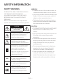
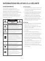
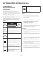
SAFETY INFORMATION
SAFETY WARNINGS
TO REDUCE THE RISK OF ELECTRIC SHOCK, DO
NOT REMOVE THE COVER (OR BACK).
NO USER-SERVICEABLE PARTS ARE INSIDE.
REFER SERVICING TO QUALIFIED SERVICE
PERSONNEL.
Refer to the table below for an explanation of
symbols which may be on your Samsung product.
CAUTION
RISK OF ELECTRIC SHOCK.
DO NOT OPEN.
This symbol indicates that high voltage
is present inside. It is dangerous to
make any kind of contact with any
internal part of this product.
This symbol indicates that this product
comes with important literature
concerning operation and maintenance.
Class II product : This symbol indicates
that a safety connection to electrical
earth (ground) is not required.
If this symbol is not present on a
product with a power cord, the product
MUST have a reliable connection to
protective earth (ground).
AC voltage : This symbol indicates that
the rated voltage marked with the
symbol is AC voltage.
DC voltage : This symbol indicates that
the rated voltage marked with the
symbol is DC voltage.
Caution. Consult Instructions for use :
This symbol instructs the user to
consult the user manual for further
safety related information.
WARNING
• To reduce the risk of re or electric shock, do
not expose this appliance to rain or moisture.
• This product contains chemicals known to the
State of California to cause cancer and birth
defects or other reproductive harm.
• The battery (battery or batteries or battery
pack) shall not be exposed to excessive heat
such as sunshine, re or the like.
CAUTION
• TO PREVENT ELECTRIC SHOCK, MATCH WIDE
BLADE OF PLUG TO WIDE SLOT, FULLY
INSERT.
• This apparatus shall always be connected to a
AC outlet with a protective grounding
connection.
• To disconnect the apparatus from the mains,
the plug must be pulled out from the mains
socket, therefore the mains plug shall be
readily operable.
• Do not expose this apparatus to dripping or
splashing. Do not put objects lled with
liquids, such as vases, on the apparatus.
• To turn this apparatus off completely, you
must pull the power plug out of the wall
socket. Consequently, the power plug must
be easily and readily accessible at all times.

ENG - iii
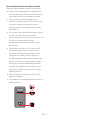
To avoid deterioration of water resistant
Check the following and use the unit correctly.
• Deformation or damage from dropping the
unit or subjecting it to mechanical shock may
cause deterioration of the water resistant.
• This unit does not have a design that is
resistant to water pressure. Use of the unit in
a location where high water pressure is
applied, such as in the shower, may cause a
malfunction.
• Do not pour high-temperature water or blow
hot air from a hair dryer or any other
applicance on the unit directly. Also never use
the unit in a place subject to high
temperatures, such as in a sauna or near a
heat source.
• Handle the cap with care. Port cover & AC
plug cover plays a very important role in
maintenance of the water resistant. When
using the unit, make sure that the cap is
closed completely. When closing the cap, be
careful not to allow foreign objects inside. If
the cap is not closed completely the water
resistant may deteriorate and may cause a
malfunction of the unit as a result of water
entering the unit.
• IPX5 cannot be met when any JACK or AC
power is plugged in.
• The product cannot be dumped to ensure it is
water resistant.
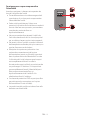
USB
(5V 0.5A)
AUX 1
POWER

ENG - iv
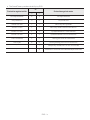
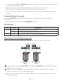
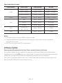
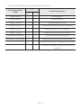
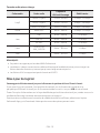
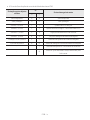
• The Sound Tower provides durability by IPX5.
Protection against solids IP Protection against water
0 5
No requirements X X No requirements
No protection 0 0 No protection
Solids> 50 mm 1 1 Vertically falling water
Solids> 12 mm 2 2 Vertically water-enclosure tilted 15°
Solids> 2.5 mm 3 3 Sprayed water 60° from vertical
Solids> 1.0 mm 4 4 Splashed water from all directions
Dust Protected 5 5 Hosing jets from all directions
Dust tight 6 6 Strong hosing jets from all directions
- 7 Temporary Immersion: 1m for 30 minutes
- 8 Immersion: manufacture dened depth and time

ENG - v
PRECAUTIONS
1. Ensure that the AC power supply in your
house complies with the power
requirements listed on the identication
sticker located on the rear of your product.
Install your product horizontally, on a
suitable base (furniture), with enough space
around it for ventilation (7~10 cm). Make sure
the ventilation slots are not covered. Do not
place the unit on ampliers or other
equipment which may become hot. This unit
is designed for continuous use.
To fully turn off the unit, disconnect the AC
plug from the wall outlet. Unplug the unit if
you intend to leave it unused for a long
period of time.
2. During thunderstorms, disconnect the AC
plug from the wall outlet. Voltage peaks due
to lightning could damage the unit.
3. Do not expose the unit to direct sunlight or
other heat sources. This could lead to
overheating and cause the unit to
malfunction.
4. Protect the product from moisture (i.e.
vases), and excess heat (e.g. a replace) or
equipment creating strong magnetic or
electric elds. Unplug the power cable from
the AC wall socket if the unit malfunctions.
Your product is not intended for industrial
use. It is for personal use only. Condensation
may occur if your product has been stored in
cold temperatures. If transporting the unit
during the winter, wait approximately
2 hours until the unit has reached room
temperature before using.
5. The battery used with this product contains
chemicals that are harmful to the
environment. Do not dispose of the battery
in the general household trash. Do not
expose the battery to excess heat, direct
sunlight, or re. Do not short circuit,
disassemble, or overheat the battery.
CAUTION : Danger of explosion if the battery
is replaced incorrectly. Replace only with the
same or equivalent type.
Others
• As the battery is manufactured only for this
product, do not use the battery for other
electronic appliances or other purposes.
• When discarding a dead battery, put it into a
battery collection box for recycling.
• Do not disassemble the battery.
• To protect the battery, the battery cannot be
charged when the temperature is lower than
3 °C or higher than 42 °C.
• When the battery level is low, recharge it. If
the level of the battery remains low for a long
period of time, it can cause the performance
of the battery to degrade.
• Do not apply heat to the battery and do not
put the battery in a re.
• Do not disassemble the battery.
• To protect the battery, the Sound Tower may
not operate when the temperature is lower
than -17 °C or higher than 57 °C.

ENG - vi
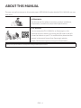
ABOUT THIS MANUAL
The user manual has two parts: this simple paper USER MANUAL and a detailed FULL MANUAL you can
download.
USER MANUAL
See this manual for safety instructions, product installation,
components, connections, and product specications.
FULL MANUAL
You can access the FULL MANUAL on Samsung’s on-line
customer support centre by scanning the QR code on the left.
To see the manual on your PC or mobile device, download the
manual in document format from Samsung’s website.
(https://www.samsung.com/us/support/downloads/)
Design and specications are subject to change without prior notice.

ENG - vii
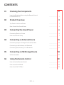
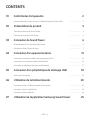
CONTENTS
01 Checking the Components 2
Inserting Batteries before using the Remote Control
(AAA batteries X 2) ------------------------- 2
02 Product Overview 3
Top Panel of the Sound Tower ------------------------- 3
Rear Panel of the Sound Tower ------------------------- 4
03 Connecting the Sound Tower 6
Connecting Electrical Power ------------------------- 6
How to use Audio Group ------------------------- 7
04 Connecting an External Device 13
Connecting using an Analogue Audio (AUX) Cable ------------------------- 13
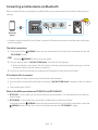
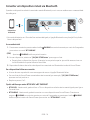
Connecting a mobile device via Bluetooth ------------------------- 14
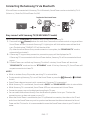
Connecting the Samsung TV via Bluetooth ------------------------- 17
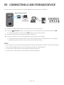
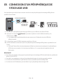
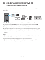
05 Connecting a USB Storage Device 18
Software Update ------------------------- 19
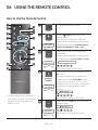
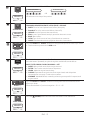
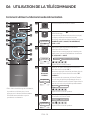
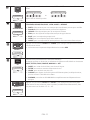
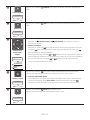
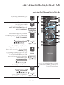
06 Using the Remote Control 20
How to Use the Remote Control ------------------------- 20
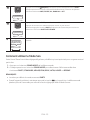
How to use Sound Mode ------------------------- 23
How to use the DJ Effect ------------------------- 23

ENG - viii
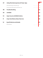
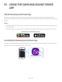
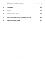
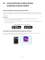
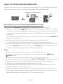
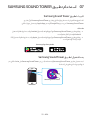
07 Using the Samsung Sound Tower App 25
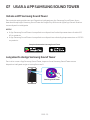
Install Samsung Sound Tower App ------------------------- 25
Launching the Samsung Sound Tower App ------------------------- 25
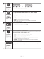
08 Troubleshooting 26
09 LICENCE 27
10 Open Source LICENCE Notice 28
11 Important Notes About Service 28
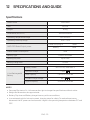
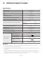
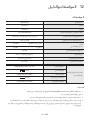
12 SpecicationsandGuide 29
Specications ------------------------- 29

ENG - 2
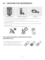
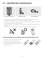
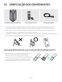
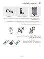
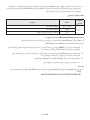
01 CHECKING THE COMPONENTS
Sound Tower Main Unit Remote Control / Batteries Power Cord
• For more information about the power supply and power consumption, refer to the label attached
to the product. (Label: Rear of the Sound Tower Main Unit)
• To purchase additional components or optional cables, contact a Samsung Service Centre or
Samsung Customer Care.
• When moving the product, do not drag or pull the product from the ground. Lift the product when
moving the product.
• Design and specications are subject to change without prior notice.
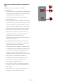
Inserting Batteries before using the Remote Control
(AAA batteries X 2)
Slide the battery cover in the direction of the arrow
until it is completely removed. Insert 2 AAA
batteries (1.5V) oriented so that their polarity is
correct. Slide the battery cover back into position.

ENG - 3
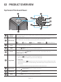
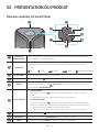
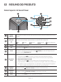
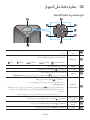
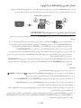
02 PRODUCT OVERVIEW
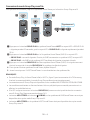
Top Panel of the Sound Tower
BASS
Remote
Sensor
When operating the Sound Tower system, please aim the front of the remote control at
the remote sensor.
LED Indicator
Displays operating messages or current source of the Sound Tower system.
The information sources represented by each LED are as follows:
(BT) (USB) (AUX1) (AUX2) (Power/Battery)
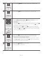
Power Turns the Sound Tower on and off.
Light Press the (Light) button to turn the Lighting Mode on.
Source
Press to select a source connected to the Sound Tower.
Press and hold the (Source)
button for more than 5 seconds
to enter the
“SEARCHING TV”
mode.
Play/Pause
• Play/Pause
Press the button to pause a music le temporarily.
When you press the button again, the music le plays.
• Demo play
Press and hold the
button for more than 5 seconds to start the Demo play while
the system is turned on. 5 LEDS ashing simultaneously and it plays demo music for
90seconds.
– Please be careful as it may play louder than the set volume.
Volume down Press the (Volume down) button to lower the volume.
Volume up Press the (Volume up) button to raise the volume.
BASS Press the BASS button to use the powerful bass sound.

ENG - 4
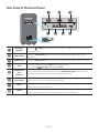
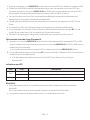
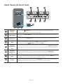
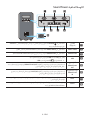
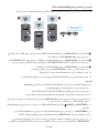
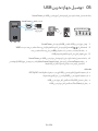
Rear Panel of the Sound Tower
USB
(5V 0.5A)
AUX 1
POWER
USB
(5V 0.5A)
AUX 1
Bluetooth
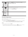
PAIRING
Press the PAIRING button to enter pairing mode, "PAIRING" LED on the rear plane
will be fast blink.
ADD STEREO Press the ADD STEREO button to connect to another same model Sound Tower
wirelessly.
GROUP PLAY Press the GROUP PLAY button to connect up to ten Sound Tower systems wirelessly.
USB Connect a USB device to the USB port on the main unit.
• Press the (Source) button to select USB.
GROUP PLAY
OUT
Terminals
Use an Audio Cable (not supplied) to connect GROUP PLAY (OUT) terminals on the
main unit to Audio In on an external analogue output device.
GROUP PLAY
IN Terminals
Use an Audio Cable (not supplied) to connect AUX2(IN) terminals on the main unit to
Audio Out on an external analogue output device.
AUX1 Use an Audio (AUX) Cable (not supplied) to connect AUX1 jack on the main unit to
Audio Out on an external device.
Power Connect the power cord to the Power jack and connect the other end of the power
cord to a wall socket to supply electrical power to the Sound Tower.

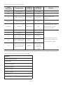
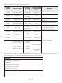
ENG - 5
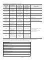
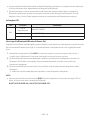
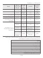
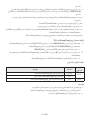
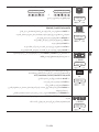
Charge LED State of the Sound Tower:
Sound
Tower state Charging state Charge LED
(AC Mode)
Charge LED
(DC Mode) Remark
Off Fully charged Off(black) Off (black)
Off Charging Green blinks N/A
Off Not in charging Off (black) Off (black) The AC cable is not
inserted.
Stand by Fully charged Blue on N/A There is no standby mode
in DC mode.
Stand by Charging Green blinks N/A
The charging LED is the
same as when Sound
Tower is shut down.
On Fully charged Blue on Blue on
When turned on, Sound
Tower mainly reects the
current battery state.
On Charging Green blinks N/A
On Not in charging and
30%~98%power Green on Green on
On Not in charging and
5% ~ 29% power Red on Red on
On Not in charging and
below 5% power Red on
Power off after
Light bar
orange blink
once
In DC mode shutdown, the entire system power will be turned off. So in the off state, compared with AC
mode, the following functions are not supported.
Feature
Wake up via bluetooth
Shop mode
Power Off Setting
Customer Reset
Power on via IR
Battery Charge
AUI on/off
UI feedback of LED lighting bar(front) on/off

ENG - 6
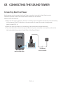
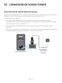
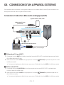
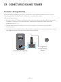
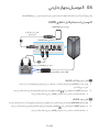
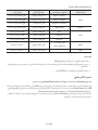
03 CONNECTING THE SOUND TOWER
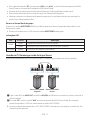
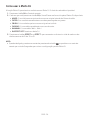
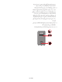
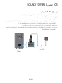
Connecting Electrical Power
Use the power cord to connect the Sound Tower to an electrical outlet in the following order:
Connect the power cord to the Sound Tower and then to a wall socket.
See the illustrations below.
• When the AC cord is pressed in, the built-in battery will be charged automatically until the battery
is fully charged. The LED indicator on the top panel will show the current charging state
(refer to page ENG - 4).
• When you unplug the set to run on battery, the volume level drops dramatically.
• For more information about the required electrical power and power consumption, refer to the
label attached to the product. (Label: Rear of the Sound Tower)
USB
(5V 0.5A)
AUX 1
POWER
Connecting
Electrical Power
Rear of Sound Tower

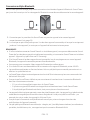
ENG - 7
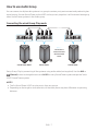
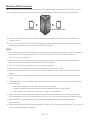
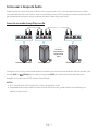
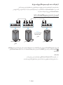
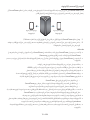
How to use Audio Group
You can connect multiple audio systems in a group to create a party environment and produce higher
sound output. Set one Sound Tower as the HOST and any music played on it will be shared among any
other Sound Tower systems in the Audio group.
Connecting the wired Group Play mode
1st
Sound Tower HOST
2nd
Sound Tower
Last
Sound Tower
Continue the
connection until
the last Sound
Tower
Set up Group Play by connecting all the systems using audio cables (not supplied). Use the AUX or
(Source) button to change the source to AUX2 for every Sound Tower system except the 1st (or
HOST) Sound Tower system.
NOTES
• The 1st Sound Tower HOST can play music from any source.
• Depending on the length or characteristics of the cable, there may be a difference in operating
distance.

ENG - 8
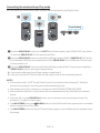
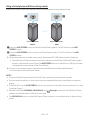
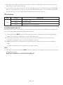
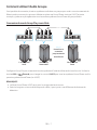
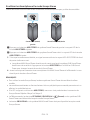
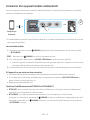
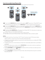
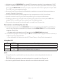
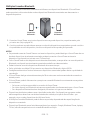
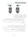
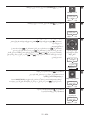
Connecting the wireless Group Play mode
You can connect up to ten Sound Tower systems with the wireless Group Play function.
POWER
POWER
POWER
HOST
SUB 1 SUB 2
Greenashing
Press the GROUP PLAY button on the HOST Sound Tower system, After “GROUP LED” solw blinks
10 seconds ”GROUP PLAY”LED will be fast blink (30s).
Press the GROUP PLAY button on the 2nd Sound Tower system (SUB 1).”GROUP PLAY”LED will be
blink.And then SUB1 will be connected with HOST,”GROUP PLAY”LED of SUB1 and HOST will stop
blinking and turn on.
Press the GROUP PLAY button on the 3rd Sound Tower system (SUB 2). Tone prompt instead the
GROUP PLAY button on the system stops blinking.
4. If you want to add more Sound Tower systems, repeat step 3.
5. Play music on the HOST Sound Tower. Sound outputs from all the connected systems.
NOTES
• In Group play mode, “HOST” Sound Tower (Figure 1) can connect to the Samsung TV. After the
connection is successful, the Group play mode automatically exits.
• The wireless Group Play connection is available for MX-ST90B/MX-ST50B/MX-ST40B.
• Environmental conditions or other factors with connected devices may have effect on playback
quality.
• If the red LED is on the GROUP PLAY button, an error has occurred in the wireless Group Play
connection. Try step 1 to step 5 again.
• The ADD STEREO button and PAIRING button on the SUB Sound Tower systems are not available
while in wireless Group Play mode.
• The ADD STEREO button on the HOST Sound Tower system is not available while in wireless Group
Play mode.

ENG - 9
• Long press “GROUP PLAY” in BT Source state to enter Group mode as “HOST”.
• All SUB units must be connected one by one. For example, after HOST is connected, press GROUP
PLAY button on SUB 1 to connect, and after SUB 1 is connected, you should connect SUB 2 and SUB
3 one by one sequentially.
• While using Group Play, currently connected Bluetooth devices are disconnected and Bluetooth
connection is disabled.
• Bluetooth devices can search and connect with the HOST Sound Tower only.
• When in Group Play mode, the SUB cannot connect to a Bluetooth device.
• If you power off and then power on the Sound Tower or select any source other than BT on a SUB
unit, in Group Play mode, the Group Play mode is disconnected.
• This product does not support aptX audio stream with Wireless Group Play mode.
Disconnecting the wireless Group Play mode
1. Press and hold the GROUP PLAY button over 5 seconds (HOST or SUB) after Group Play is
connected or press the GROUP PLAY button (HOST or SUB) before Group Play is connected.
• Tone prompt instead and the LED above the GROUP PLAY button is off.
2. If you select any source other than BT on the SUB units or turn off the HOST Sound Tower, the
Group Play mode is disconnected.
• If the disconnection is made from the HOST Sound Tower, Group Play is disconnected.
LED Indications
LED STATE Description
Green Blink Waiting for a wireless Group Play connection.
Solid The wireless Group Play connection was successful.
Red Solid There is an error with the wireless Group Play connection.
NOTE
• In wireless connection, Playback quality can be unstable depending on Bluetooth environment.
For better play, please keep the device in wired Group Play mode.
• The rst bluetooth connection should be within 1m.

ENG - 10
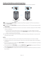
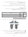
Using a Smartphone and Stereo Group mode
Connect two Sound Tower and use them with your smartphone to enjoy stereo sound.
Left Sound Tower
(MAIN)
Right Sound Tower
(SUB)
Press the ADD STEREO button on the left Sound Tower system. The LED blinks on the ADD
STEREO button.
Press the ADD STEREO button on the right Sound Tower system. The LED blinks on the ADD
STEREO button.
3. When the connection is made, tone prompt. Backplane ADD LED Green Indicator Steady on.
• The MAIN Sound Tower system outputs left channel sound and the SUB Sound Tower system
outputs right channel sound. Press the ADD STEREO button on the MAIN or SUB Sound Tower
to change the sound channel of the Sound Tower.
4. Play music by connecting your smartphone to the MAIN Sound Tower and Bluetooth.
Sound is output from both Sound Tower.
NOTES
• To use the Stereo Group mode, both Sound Tower systems must be the same model.
• Environmental conditions or other factors with connected devices may have effect on playback
quality.
• If the red LED is on the ADD STEREO, an error has occured in the Stereo Group connection. Try step
1 and step 3 again.
• Remote Controller, BT PAIRING, GROUP PLAY and (Source) buttons on the SUB Sound Tower
systems are disabled while in Stereo Group mode.
• The GROUP PLAY button on the MAIN Sound Tower system is not available while in Stereo Group
mode.

ENG - 11
• In mode other than “BT” (ex. USB, AUX mode), music is played only in MAIN Sound Tower and music
is not played in SUB Sound Tower.
• The lighting colours between MAIN Sound Tower and SUB Sound Tower may vary.
• This product does not support aptX audio stream with Stereo Group mode.
• If you try to connect a Bluetooth device while Stereo Group is connecting, the Stereo Group mode
may fail.
Terminate the Stereo Group mode
Press the ADD STEREO button (MAIN or SUB) for at least 5 seconds while the Stereo Group is
connected.
• Tone prompt and the LED above the ADD STEREO button is off.
LED Indications
LED STATE Description
Green Blink Waiting for a Stereo Group connection.
Solid The Stereo Group connection is successful.
Red Solid There is an error with the Stereo Group connection.
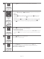
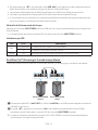
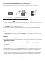
Using Samsung TV and Stereo Group mode
Connect two Sound Tower by wire and use them with Samsung TV to enjoy stereo sound.
Left Sound Tower
(MAIN)
Right Sound Tower
(SUB)
Connect the RCA cable to the AUX2 OUT on the MAIN and AUX2 IN on the SUB as shown by using
the RCA cable (not supplied).
In “BT” mode, press the “AUX” button on the MAIN Sound Tower remote control for at least 5
seconds. The LED blinks on the ADD STEREO button.
3. When the connection is complete, the “ADD STEREO” LED turn on and then the current output.
Tone prompt instead.

ENG - 12
4. When the connection is complete, the SUB top panel “AUX2” LED turn on.
• The MAIN Sound Tower outputs the left channel sound and the SUB Sound Tower outputs the
right channel sound. Press the ADD STEREO button on the MAIN or SUB Sound Tower to
change the sound channel of the Sound Tower.
5. Connect a TV and MAIN Sound Tower via Bluetooth to play music. Sound is output from both
Sound Tower.
NOTES
• To use Stereo Group mode, both Sound Tower must be the same model.
• A red light on the LED on the ADD STEREO button indicates an error in the Stereo Group
connection. Try Step 1 to 5 again.
• In Stereo Group mode, the remote control, BT PAIRING, GROUP PLAY, and (Source) buttons on
the SUB Sound Tower are disabled.
• The GROUP PLAY button on the MAIN Sound Tower is not available in Stereo Group mode.
• If Samsung TV supports a simple connection, the connection pop-up is automatically displayed on
the TV, and if you select “Yes”, it connects to the TV. If there is a previous connection history
between Samsung TV and Sound Tower, it will be connected to Samsung TV without pop-up. For a
simple connection to Samsung TV, refer to page 17.
• The lighting colours may vary between the MAIN Sound Tower and the SUB Sound Tower.
Terminating the Stereo Group mode connection
Press the ADD STEREO button (MAIN or SUB) for at least 5 seconds after the Stereo Group is
connected.
• “OFF-STEREO MODE” tone prompt and the LED on the ADD STEREO button turns off.

ENG - 13
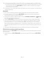
04 CONNECTING AN EXTERNAL DEVICE
Connect to an external device via a wired or wireless network to play the external device’s sound
through the Sound Tower.
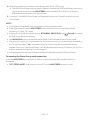
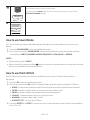
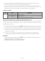
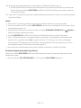
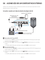
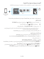
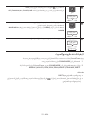
Connecting using an Analogue Audio (AUX) Cable
AUX 1
- AUDIO -
R L
Mobile device / MP3 / PMP
BD / DVD player / Set-top box / Game console
3.5mm
stereo cable (not supplied)
Audio (AUX) Cable (not supplied)
Rear of the Sound Tower
3.5mm stereo Cable (AUX1)
1. Connect AUX1 jack on the main unit to the AUDIO OUT jack of the Source Device using an 3.5mm
stereo cable.
2. Select “AUX1” mode by pressing the (Source) button on the top panel or on the remote control.
• You can also select a source using AUX button on the remote control.
Audio Cable (AUX2)
1. Connect AUX2 (IN) terminals on the main unit to the AUDIO OUT terminals of the Source Device
using an audio cable.
2. Select “AUX2” mode by pressing the (Source) button on the top panel or on the remote
control.
• You can also select a source using AUX button on the remote control.
A página está carregando ...
A página está carregando ...
A página está carregando ...
A página está carregando ...
A página está carregando ...
A página está carregando ...
A página está carregando ...
A página está carregando ...
A página está carregando ...
A página está carregando ...
A página está carregando ...
A página está carregando ...
A página está carregando ...
A página está carregando ...
A página está carregando ...
A página está carregando ...
A página está carregando ...
A página está carregando ...
A página está carregando ...
A página está carregando ...
A página está carregando ...
A página está carregando ...
A página está carregando ...
A página está carregando ...
A página está carregando ...
A página está carregando ...
A página está carregando ...
A página está carregando ...
A página está carregando ...
A página está carregando ...
A página está carregando ...
A página está carregando ...
A página está carregando ...
A página está carregando ...
A página está carregando ...
A página está carregando ...
A página está carregando ...
A página está carregando ...
A página está carregando ...
A página está carregando ...
A página está carregando ...
A página está carregando ...
A página está carregando ...
A página está carregando ...
A página está carregando ...
A página está carregando ...
A página está carregando ...
A página está carregando ...
A página está carregando ...
A página está carregando ...
A página está carregando ...
A página está carregando ...
A página está carregando ...
A página está carregando ...
A página está carregando ...
A página está carregando ...
A página está carregando ...
A página está carregando ...
A página está carregando ...
A página está carregando ...
A página está carregando ...
A página está carregando ...
A página está carregando ...
A página está carregando ...
A página está carregando ...
A página está carregando ...
A página está carregando ...
A página está carregando ...
A página está carregando ...
A página está carregando ...
A página está carregando ...
A página está carregando ...
A página está carregando ...
A página está carregando ...
A página está carregando ...
A página está carregando ...
A página está carregando ...
A página está carregando ...
A página está carregando ...
A página está carregando ...
A página está carregando ...
A página está carregando ...
A página está carregando ...
A página está carregando ...
A página está carregando ...
A página está carregando ...
A página está carregando ...
A página está carregando ...
A página está carregando ...
A página está carregando ...
A página está carregando ...
A página está carregando ...
A página está carregando ...
A página está carregando ...
A página está carregando ...
A página está carregando ...
A página está carregando ...
A página está carregando ...
A página está carregando ...
A página está carregando ...
A página está carregando ...
A página está carregando ...
A página está carregando ...
A página está carregando ...
A página está carregando ...
A página está carregando ...
A página está carregando ...
A página está carregando ...
A página está carregando ...
A página está carregando ...
A página está carregando ...
A página está carregando ...
A página está carregando ...
A página está carregando ...
A página está carregando ...
A página está carregando ...
A página está carregando ...
A página está carregando ...
A página está carregando ...
A página está carregando ...
A página está carregando ...
A página está carregando ...
-
 1
1
-
 2
2
-
 3
3
-
 4
4
-
 5
5
-
 6
6
-
 7
7
-
 8
8
-
 9
9
-
 10
10
-
 11
11
-
 12
12
-
 13
13
-
 14
14
-
 15
15
-
 16
16
-
 17
17
-
 18
18
-
 19
19
-
 20
20
-
 21
21
-
 22
22
-
 23
23
-
 24
24
-
 25
25
-
 26
26
-
 27
27
-
 28
28
-
 29
29
-
 30
30
-
 31
31
-
 32
32
-
 33
33
-
 34
34
-
 35
35
-
 36
36
-
 37
37
-
 38
38
-
 39
39
-
 40
40
-
 41
41
-
 42
42
-
 43
43
-
 44
44
-
 45
45
-
 46
46
-
 47
47
-
 48
48
-
 49
49
-
 50
50
-
 51
51
-
 52
52
-
 53
53
-
 54
54
-
 55
55
-
 56
56
-
 57
57
-
 58
58
-
 59
59
-
 60
60
-
 61
61
-
 62
62
-
 63
63
-
 64
64
-
 65
65
-
 66
66
-
 67
67
-
 68
68
-
 69
69
-
 70
70
-
 71
71
-
 72
72
-
 73
73
-
 74
74
-
 75
75
-
 76
76
-
 77
77
-
 78
78
-
 79
79
-
 80
80
-
 81
81
-
 82
82
-
 83
83
-
 84
84
-
 85
85
-
 86
86
-
 87
87
-
 88
88
-
 89
89
-
 90
90
-
 91
91
-
 92
92
-
 93
93
-
 94
94
-
 95
95
-
 96
96
-
 97
97
-
 98
98
-
 99
99
-
 100
100
-
 101
101
-
 102
102
-
 103
103
-
 104
104
-
 105
105
-
 106
106
-
 107
107
-
 108
108
-
 109
109
-
 110
110
-
 111
111
-
 112
112
-
 113
113
-
 114
114
-
 115
115
-
 116
116
-
 117
117
-
 118
118
-
 119
119
-
 120
120
-
 121
121
-
 122
122
-
 123
123
-
 124
124
-
 125
125
-
 126
126
-
 127
127
-
 128
128
-
 129
129
-
 130
130
-
 131
131
-
 132
132
-
 133
133
-
 134
134
-
 135
135
-
 136
136
-
 137
137
-
 138
138
-
 139
139
-
 140
140
-
 141
141
-
 142
142


