Stanley 74200 Blind Rivet Nut Tool Manual do usuário
- Categoria
- Ferramentas elétricas
- Tipo
- Manual do usuário

INSTRUCTION AND
SERVICE MANUAL
ORIGINAL INSTRUCTION
Blind Rivet Nut Tool - 74200
Hydro-Pneumatic Power Tool
EN
Hydro-Pneumatic Power Tool
FRC
Outil électrique hydropneumatique
ESM
Herramienta hidroneumática
PTB
Ferramenta Elétrica Hidropneumática

©2021 Stanley Black & Decker inc. All rights reserved.
The information provided may not be reproduced and/or made public in any way and through any means (electronically or
mechanically) without prior explicit and written permission from STANLEY Engineered Fastening. The information provided
is based on the data known at the moment of the introduction of this product. STANLEY Engineered Fastening pursues a
policy of continuous product improvement and therefore the products may be subject to change. The information provided
is applicable to the product as delivered by STANLEY Engineered Fastening. Therefore, STANLEY Engineered Fastening
cannot be held liable for any damage resulting from deviations from the original specications of the product.
The information available has been composed with the utmost care. However, STANLEY Engineered Fastening will not
accept any liability with respect to any faults in the information nor for the consequences thereof. STANLEY Engineered
Fastening will not accept any liability for damage resulting from activities carried out by third parties. The working names,
trade names, registered trademarks, etc. used by STANLEY Engineered Fastening should not be considered as being free,
pursuant to the legislation with respect to the protection of trade marks.
2
ENGLISH ORIGINAL INSTRUCTION

1. SAFETY DEFINITIONS ................................................................................................................................................... 4
1.1 GENERAL SAFETY RULES .......................................................................................................................................................................... 4
1.2 PROJECTILE HAZARDS .............................................................................................................................................................................. 4
1.3 OPERATING HAZARDS ............................................................................................................................................................................... 5
1.4 REPETITIVE MOTIONS HAZARDS............................................................................................................................................................ 5
1.5 ACCESSORY HAZARDS .............................................................................................................................................................................. 5
1.6 WORKPLACE HAZARDS ............................................................................................................................................................................. 5
1.7 NOISE HAZARDS .......................................................................................................................................................................................... 5
1.8 VIBRATION HAZARDS................................................................................................................................................................................. 6
1.9 ADDITIONAL SAFETY INSTRUCTION FOR PNEUMATIC POWER TOOLS ................................................................................... 6
2. SPECIFICATIONS ............................................................................................................................................................ 7
2.1 PLACING TOOL SPECIFICATION .............................................................................................................................................................. 7
2.2 TOOL DIMENSIONS ..................................................................................................................................................................................... 7
3. INTENT OF USE .............................................................................................................................................................. 8
4.1 AIR SUPPLY .................................................................................................................................................................................................... 8
4.2 STROKE ADJUSTMENT ............................................................................................................................................................................... 9
4.3 PRINCIPLE OF OPERATION ....................................................................................................................................................................... 9
5. NOSE ASSEMBLIES ......................................................................................................................................................10
5.1 FITTING INSTRUCTIONS .......................................................................................................................................................................... 10
5.2 SERVICE INSTRUCTIONS .........................................................................................................................................................................10
5.3 74200 NOSE ASSEMBLY COMPONENTS ............................................................................................................................................10
6. SERVICING THE TOOL..................................................................................................................................................13
6.1 DAILY SERVICING ....................................................................................................................................................................................... 13
6.2 WEEKLY SERVICING ...................................................................................................................................................................................13
6.3 SERVICE KIT ..................................................................................................................................................................................................13
6.4 MAINTENANCE ........................................................................................................................................................................................... 14
6.5 PNEUMATIC CYLINDER ............................................................................................................................................................................ 14
6.6 ROD GUIDE .................................................................................................................................................................................................. 14
6.7 TRIGGER ........................................................................................................................................................................................................ 14
6.8 SWIVEL AIR INLET (74200-12700) ........................................................................................................................................................ 15
6.9 DIFFERENTIAL VALVE................................................................................................................................................................................15
6.10 HEAD ASSEMBLY .......................................................................................................................................................................................15
6.11 REAR CASING .............................................................................................................................................................................................. 15
6.12 DISTRIBUTOR ..............................................................................................................................................................................................15
6.13 HYDRAULIC PISTON & AIR MOTOR ASSEMBLY (74200-12610) .................................................................................................15
6.14 MOLYKOTE 55m SAFETY DATA ............................................................................................................................................................. 17
6.15 PROTECTING THE ENVIRONMENT .......................................................................................................................................................17
7. GENERAL ASSEMBLIES ...............................................................................................................................................18
7.1 GENERAL ASSEMBLY OF BASE TOOL 74200-12000 .......................................................................................................................18
7.2 GENERAL ASSEMBLY PARTS LIST 74200-12000 ..............................................................................................................................19
8. PRIMING ......................................................................................................................................................................20
8.1 OIL DETAILS ................................................................................................................................................................................................. 20
8.2 HYSPIN®VG 32 OIL SAFETY DATA .........................................................................................................................................................20
8.3 PRIMING PROCEDURCE ...........................................................................................................................................................................20
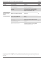
9. FAULT DIAGNOSIS ....................................................................................................................................................... 21
10. EC DECLARATION OF CONFORMITY .......................................................................................................................... 23
11. UK DECLARATION OF CONFORMITY .........................................................................................................................24
12. PROTECT YOUR INVESTMENT! ...................................................................................................................................25
3
ORIGINAL INSTRUCTION ENGLISH

This instruction manual must be read by any person installing or operating this tool with particular attention to the
following safety rules.
Always wear impact-resistant eye protection during operation of the tool. The grade of protection required should
be assessed for each use.
Use hearing protection in accordance with employer’sinstructions and as required by occupational health and
safety regulations.
Use of the tool can expose the operator’shands to hazards, including crushing, impacts, cuts and abrasions and
heat. Wear suitable gloves to protect hands.
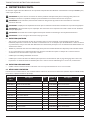
1. SAFETY DEFINITIONS
The denitions below describe the level of severity for each signal word. Please read the manual and pay attention to these symbols.
DANGER: Indicates an imminently hazardous situation which, if not avoided, will result in death or serious injury.
WARNING: Indicates apotentially hazardous situation which, if not avoided, could result in death or serious injury.
CAUTION: Indicates apotentially hazardous situation which, if not avoided, may result in minor or moderate injury.
CAUTION: Used without the safety alert symbol indicates apotentially hazardous situation which, if not avoided, may
result in property damage.
Improper operation or maintenance of this product could result in serious injury and property damage. Read and
understand all warnings and operating instructions before using this equipment. When using power tools, basic safety
precautions must always be followed to reduce the risk of personal injury.
SAVE ALL WARNINGS AND INSTRUCTIONS FOR FUTURE REFERENCE
1.1 GENERAL SAFETY RULES
• For multiple hazards, read and understand the safety instructions before installing, operating, repairing, maintaining,
changing accessories on, or working near the tool. Failure to do so can result in serious bodily injury.
• Only qualied and trained operators must install, adjust or use the tool.
• DO NOT use outside the design intent of placing STANLEY Engineered Fastening Blind Rivet Nuts.
• Use only parts, fasteners, and accessories recommended by the manufacturer.
• DO NOT modify the tool. Modication can reduce the eectiveness of safety measures and increase the risks to the
operate. Any modication to the tool undertaken by the customer will be customer’s entire responsibility and void any
applicable warranties.
• Do not discard the safety instructions; give them to the operator.
• Do not use the tool if it has been damaged.
• Prior to use, check for misalignment or binding of moving parts, breakage of parts, and any other condition that aects
the tool’s operation. If damaged, have the tool serviced before using. Remove any adjusting key or wrench before use.
• Tools shall be inspected periodically to verify that the ratings and markings required by this part of ISO 11148 are
legibly marked on the tool. The employer/user shall contact the manufacturer to obtain replacement marking labels
when necessary.
• The tool must be maintained in a safe working condition at all times and examined at regular intervals for damage
and function by trained personnel. Any dismantling procedure will be undertaken only by trained personnel. Do not
dismantle this tool without prior reference to the maintenance instructions.
1.2 PROJECTILE HAZARDS
• Disconnect the air supply from the tool before performing any maintenance, attempting to adjust, t or remove a nose
assembly or accessories.
• Be aware that failure of the workpiece or accessories or even of the inserted tool itself can generate high- velocity
projectiles.
• Always wear impact-resistant eye protection during operation of the tool. The grade of protection required should be
assessed for each use.
• The risks to others should also be assessed at this time.
• Ensure that the workpiece is securely xed.
• Check that the means of protection from ejection of fastener and/or mandrel is in place and is operative.
4
ENGLISH ORIGINAL INSTRUCTION

• DO NOT use the tool without mandrel collector installed.
• Warn against the possible forcible ejection of mandrels from the front of the tool.
• DO NOT operate a tool that is directed towards any person(s).
1.3 OPERATING HAZARDS
• Use of the tool can expose the operator's hands to hazards, including crushing, impacts, cuts and abrasions and heat.
Wear suitable gloves to protect hands.
• Operators and maintenance personnel shall be physically able to handle the bulk, weight and power of the tool.
• Hold the tool correctly; be ready to counteract normal or sudden movements and have both hands available.
• Keep tool handles dry, clean, and free from oil and grease.
• Maintain a balanced body position and secure footing when operating the tool.
• Release the start-and-stop device in the case of an interruption of the air supply.
• Use only lubricants recommended by the manufacturer.
• Contact with hydraulic uid should be avoided. To minimize the possibility of rashes, care should be taken to wash
thoroughly if contact occurs.
• Material Safety Data Sheets for all hydraulic oils and lubricants is available on request from your tool supplier.
• Avoid unsuitable postures, as it is likely for these positions not to allow counteracting of normal or unexpected
movement of the tool.
• If the tool is xed to a suspension device, make sure that the xation is secure.
• Beware of the risk of crushing or pinching if nose equipment is not tted.
• DO NOT operate tool with the nose casing removed.
• Adequate clearance is required for the tool operator’s hands before proceeding.
• When carrying the tool from place to place keep hands away from the trigger to avoid inadvertent activation.
• DO NOT abuse the tool by dropping or using it as a hammer.
1.4 REPETITIVE MOTIONS HAZARDS
• When using the tool, the operator can experience discomfort in the hands, arms, shoulders, neck or other parts of the
body.
• While using the tool, the operator should adopt a comfortable posture whilst maintaining a secure footing and
avoiding awkward or o-balance postures. The operator should change posture during extended tasks; this can help
avoid discomfort and fatigue.
• If the operator experiences symptoms such as persistent or recurring discomfort, pain, throbbing, aching, tingling,
numbness, burning sensations or stiness, these warning signs should not be ignored. The operator should tell the
employer and consult a qualied health professional.
1.5 ACCESSORY HAZARDS
• Disconnect the tool from the air supply before tting or removing the nose assembly or accessory.
• Use only sizes and types of accessories and consumables that are recommended by the manufacturer of the tool; do
not use other types or sizes of accessories or consumables.
1.6 WORKPLACE HAZARDS
• Slips, trips and falls are major causes of workplace injury. Be aware of slippery surfaces caused by use of the tool and of
trip hazards caused by the air line or hydraulic hose.
• Proceed with care in unfamiliar surroundings. There can be hidden hazards, such as electricity or other utility lines.
• The tool is not intended for use in potentially explosive atmospheres and is not insulated against contact with electric
power.
• Ensure that there are no electrical cables, gas pipes, etc., which can cause a hazard if damaged by use of the tool.
• Dress properly. Do not wear loose clothing or jewellery. Keep your hair, clothing and gloves away from moving parts.
Loose clothes, jewellery or long hair can be caught in moving parts.
1.7 NOISE HAZARDS
• Exposure to high noise levels can cause permanent, disabling hearing loss and other problems, such as tinnitus (ringing,
buzzing, whistling or humming in the ears). Therefore, risk assessment and the implementation of appropriate controls
for these hazards are essential.
• Appropriate controls to reduce the risk may include actions such as damping materials to prevent workpieces from “ringing”.
5
ORIGINAL INSTRUCTION ENGLISH

• Use hearing protection in accordance with employer's instructions and as required by occupational health and safety
regulations.
• Select, maintain and replace the consumable/inserted tool as recommended in the instruction handbook, to prevent an
unnecessary increase in noise.
1.8 VIBRATION HAZARDS
• Exposure to vibration can cause disabling damage to the nerves and blood supply of the hands and arms.
• Wear warm clothing when working in cold conditions and keep your hands warm and dry. If you experience numbness,
tingling, pain or whitening of the skin in your ngers or hands, stop using the tool, tell your employer and consult a
physician.
• Where possible Support the weight of the tool in a stand, tensioner or balancer, because a lighter grip can then be used
to support the tool.
• Operate and maintain the assembly power tool for blind rivet nut fasteners as recommended in the instruction’s
handbook, to prevent an unnecessary increase in vibration levels.
• Select, maintain and replace the consumable/inserted tool as recommended in the instruction handbook, to prevent an
unnecessary increase in vibration levels.
• Hold the tool with a light but safe grip, taking account of the required hand reaction forces, because the risk from
vibration is generally greater when the grip force is higher.
1.9 ADDITIONAL SAFETY INSTRUCTION FOR PNEUMATIC POWER TOOLS
• The operating supply air must not exceed 7 bar (102 PSI).
• Air under pressure can cause severe injury.
• Never leave operating tool unattended. Disconnect air hose when tool is not in use, before changing accessories or
when making repairs.
• Never direct air at yourself or anyone else.
• Whipping hoses can cause severe injury. Always check for damaged or loose hoses and ttings.
• Prior to use, inspect airlines for damage, all connections must be secure. Do not drop heavy objects on hoses. A sharp
impact may cause internal damage and lead to premature hose failure.
• Cold air shall be directed away from hands.
• Whenever universal twist couplings (claw couplings) are used, lock pins shall be installed and whip check safety cables
shall be used to safeguard against possible hose-to-tool or hose-to-hose connection failure.
• DO NOT lift the placing tool by the hose. Always use the placing tool handle.
• Vent holes must not become blocked or covered.
• Keep dirt and foreign matter out of the hydraulic system of the tool as this will cause the tool to malfunction.
6
ENGLISH ORIGINAL INSTRUCTION

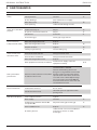
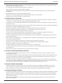
2. SPECIFICATIONS
2.1 PLACING TOOL SPECIFICATION
Air Pressure Minimum - Maximum 5-7 bar (75-100 lbf/in)
Free Air Volume Required @ 5 bar/75 lbf/in 8 litres (0.28 ft)
Stroke Maximum 7 mm (0.276 in)
Motor Speed Spin On 2000 rpm
Spin O 2000 rpm
Pull Force @ 5 bar/75 lbf/in 19.1 kN (4300 lbf)
Cycle time Approximately 2.5 seconds
Weight Without nose equipment 2.2 kg (4.85 lb)
Noise values determined according to noise test code ISO 15744 and ISO 3744. 74200
A-weighted sound power level dB(A), LWA Uncertainty noise: kWA = 3.0 dB(A) 74.70 dB(A)
A-weighted emission sound pressure level at the work station
dB(A), LpA
Uncertainty noise: kpA = 3.0 dB(A) 77.08 dB(A)
C-weighted peak emission sound pressure level dB(C), LpC, peak Uncertainty noise: kpC = 3.0 dB(C) 75.54 dB(C)
Vibration values determined according to vibration test code ISO 20643 and ISO 5349. 74200
Vibration emission level, ahd:Uncertainty vibration: k = 0.127 m/s 0.317 m/s
Declared vibration emission values in accordance with EN 12096
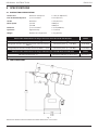
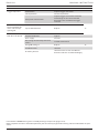
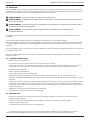
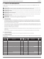
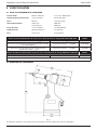
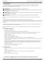
2.2 TOOL DIMENSIONS
Fig. 1
Dimensions shown in bold are millimeters. Other dimensions are in inches.
7
ORIGINAL INSTRUCTION ENGLISH

3. INTENT OF USE
The hydro-pneumatic 74200 tool is designed to place Stanley Engineered Fastening Blind Rivet Nuts at high speed making it
ideal for batch or ow-line assembly in a wide variety of applications throughout all industries.
A complete tool is made up of the base tool (part number 74200-12000) and the appropriate nose assembly for the
insert, as described on page 10.
NOSE ASSEMBLIES MUST BE FITTED AS DESCRIBED ON PAGE 10.
DO NOT use under wet conditions or in the presence of ammable liquids or gases.
4. PUTTING INTO SERVICE
IMPORTANT - READ THE SAFETY RULES ON PAGE 4 - 6 CAREFULLY BEFORE PUTTING INTO
SERVICE.
Select relevant size nose equipment and install.
Connect the placing tool to the air supply. Test pull and return cycles by depressing and releasing the trigger 25. Set the tool
for desired stroke/pressure.
CAUTION - Correct supply pressure is important for proper function of the installation tool. Personal injury or
damage to equipment may occur without correct pressures. The supply pressure must not exceed that listed in
the placing tool specication.
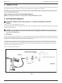
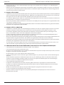
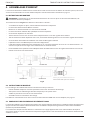
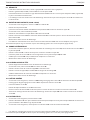
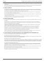
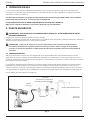
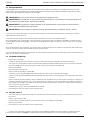
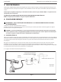
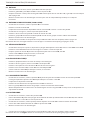
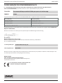
4.1 AIR SUPPLY
All tools are operated with compressed air at an optimum pressure of 5.5 bar. We recommend the use of pressure regulators
and automatic oiling/ltering systems on the main air supply. These should be tted within 3 metres of the tool (see diagram
below) to ensure maximum tool life and minimum tool maintenance.
Air supply hoses should have a minimum working eective pressure rating of 150% of the maximum pressure produced
in the system or 10 bar, whichever is the highest. Air hoses should be oil resistant, have an abrasion resistant exterior and
should be armoured where operating conditions may result in hoses being damaged. All air hoses MUST have a minimum
bore diameter of 6.4 millimetres or 1/4 inch.
Read servicing daily details page 13.
14
2
1
14
2
8
TAKE OFF POINT FROM MAIN SUPPLY
(USED DURING MAINTENANCE OF
FILTER/REGULATOR OR LUBRICATION
UNITS)
MAIN SUPPLY
DRAIN POINT
3 METRES
MAXIMUM
STOP CLOCK
LUBRICATOR
Fig. 2
8
ENGLISH ORIGINAL INSTRUCTION

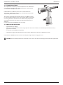
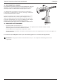
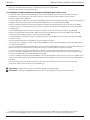
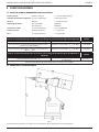
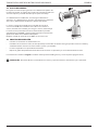
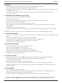
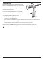
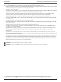
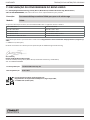
4.2 STROKE ADJUSTMENT
This adjustment is necessary to ensure optimum insert deformation.
It is suggested, therefore, that a test plate with the same thickness
and hole size as workpiece be used.
If deformation is insucient, the insert will rotate inside the
application. If deformation is excessive, thread distortion will occur
and possibly drive screw fracture.
The stroke is adjusted by the amount the rear casing 86 is screwed
in or out. To shorten stroke, screw in; to lengthen stroke, unscrew the
rear casing but never more than 5 turns from the fully “IN” position
unless dismantling the tool. Adjust until optimum deformation is
obtained.
Lock the stroke set nger 88 into the rear casing.
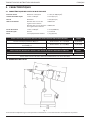
4.3 PRINCIPLE OF OPERATION
• Connect tool to air supply.
• Oer up insert, lip rst to drive screw. A light pressure will start the motor and automatically thread the insert up
against nose and stop.
• Insert fastener into application squarely.
• Fully depress trigger. This will both place insert into the application and reverse it o the drive screw.
Item numbers in bold refer to the General Assembly drawing and parts list (pages 18-19).
CAUTION - do not attempt to force the installation of an insert as this will cause damage to the tool and/or application.
Fig. 3
9
ORIGINAL INSTRUCTION ENGLISH

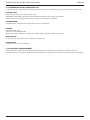
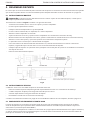
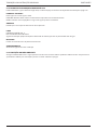
5. NOSE ASSEMBLIES
It is essential that the correct nose assembly is tted prior to operating the tool. By knowing the details of the fastener to be
placed, you will be able to order a new complete nose assembly using the selection tables on page 13.
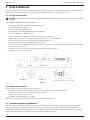
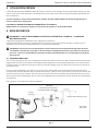
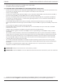
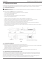
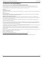
5.1 FITTING INSTRUCTIONS
CAUTION: The air supply must be disconnected when tting or removing nose assemblies unless specically instructed
otherwise.
Item numbers in bold refer to illustration below:
• If still tted remove the nose casing and the adaptor nut.
• Insert drive shaft 4 into spindle.
• Fit drive screw 3 onto drive shaft 4.
• Insert reducing sleeve 5 (if specied) into the adaptor nut.
• Screw the adaptor nut onto the spindle.
• Hold the spindle with a spanner* and tighten the adaptor nut clockwise.
• While holding the adaptor nut with the spanner*, tighten the lock nut anti-clockwise.
• Screw on the nose casing and nose tip 1 with the nose tip lock nut.
• The reverse operation is carried out for equipment removal.
• With tool still disconnected from air supply, screw one insert onto drive screw manually - making sure the insert is ush
with the end of drive screw.
• Set nose tip in exact position and lock nose tip nut clockwise with a spanner*.
• Remove the insert from drive screw.
Fig. 4
LOCK NUT
ADAPTOR NUT NOSE CASING It
ems in grey are included in the base tool.
Items in black make up the nose assembly.
SPINDLE FRICTION RING
5.2 SERVICE INSTRUCTIONS
Nose assemblies should be serviced at weekly intervals.
• Remove the complete nose assembly using the reverse procedure to the ‘Fitting Instructions’.
• Any worn or damaged part should be replaced by a new part.
• Particularly check wear on drive screw.
• Assemble according to tting instructions.
Refers to items included in the 74200 service kit. For complete list see page 13.
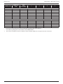
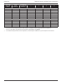
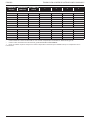
5.3 74200 NOSE ASSEMBLY COMPONENTS
Nose tips vary in shape according to the insert type. Each nose assembly represents a unique assembly of components
which can be ordered individually. All nose assemblies also include a nose tip locknut 2 (part number 07555-00901).
Component numbers refer to the illustration on the opposite page. We recommend some stock as items will need regular
replacement. Read the Nose Assemblies servicing instructions opposite carefully.
10
ENGLISH ORIGINAL INSTRUCTION

INSERT SIZE COMPLETE
TOOL
NOSE
ASSEMBLY 1345
LARGEFLANGEINSERTS (9698,FS58,9408,9418,9498)+STANDARDNUTSERT®(9500)+SQUARESERT®(GK08)+EUROSERT®(GJ08)
M3 74200-00083 07555-09883 07555-00903 07555-09003 07555-01003 07555-09103
M4 74200-00084 07555-09884 07555-00904 07555-09004 07555-01004 07555-09104
M5• 74200-00085 07555-09885 07555-00905 07555-09005 07555-01005 07555-09105
M5•• 74200-00485 07555-09185 07555-00915 07555-09005 07555-01005 07555-09105
M6 74200-00086 07555-09886 07555-00906 07555-09006 07555-01006 07555-09106
M8 74200-00088 07555-09888 07555-00908 07555-09008 07555-01008 07555-09108
M10 74200-00080 07555-09880 07555-00910 07555-09010 07555-01010 –
M12 74200-00082 74200-09882 † 07555-00912 07555-09012 07555-01012 –
4 UNC 74200-00054 07555-09854 07555-00854 07555-09054 07555-00754 07555-09154
6 UNC 74200-00056 07555-09856 07555-00856 07555-09056 07555-00756 07555-09156
8 UNC 74200-00058 07555-09858 07555-00858 07555-09058 07555-00758 07555-09158
10 UNC 74200-00050 07555-09850 07555-00850 07555-09050 07555-00750 07555-09150
1/4 UNC 74200-00048 07555-09848 07555-00848 07555-09048 07555-00748 07555-09148
5/16 UNC 74200-00040 07555-09840 07555-00840 07555-09040 07555-00740 07555-09140
3/8 UNC 74200-00042 07555-09842 07555-00842 07555-09042 07555-00742 –
10 UNF 74200-00070 07555-09870 07555-00850 07555-09070 07555-00750 07555-09150
1/4 UNF 74200-00068 07555-09868 07555-00848 07555-09068 07555-00748 07555-09148
5/16 UNF 74200-00060 07555-09860 07555-00840 07555-09060 07555-00740 07555-09140
3/8 UNF 74200-00062 07555-09862 07555-00842 07555-09062 07555-00742 –
3/16 BSW 74200-00016 07555-09816 07555-00850 07555-09016 07555-00750 07555-09150
1/4 BSW 74200-00018 07555-09818 07555-00848 07555-09018 07555-00748 07555-09148
5/16 BSW 74200-00010 07555-09810 07555-00840 07555-09019 07555-00740 07555-09140
THIN SHEET NUTSERT® (9468, FS38, 9658, 9488)
M3 74200-00183 07555-09983 07555-00993 07555-09003 07555-01003 07555-09103
M4 74200-00184 07555-09984 07555-00994 07555-09004 07555-01004 07555-09104
M5 74200-00185 07555-09985 07555-00995 07555-09005 07555-01005 07555-09105
M6 74200-00186 07555-09986 07555-00996 07555-09006 07555-01006 07555-09106
M8 74200-00188 07555-09988 07555-00998 07555-09008 07555-01008 07555-09108
M10 74200-00180 07555-09980 07555-00999 07555-09010 07555-01010 –
M12 74200-00182 74200-09982 † 07555-00992 07555-09012 07555-01012 –
4 UNC 74200-00154 07555-09954 07555-00954 07555-09054 07555-00754 07555-09154
6 UNC 74200-00156 07555-09956 07555-00956 07555-09056 07555-00756 07555-09156
8 UNC 74200-00158 07555-09958 07555-00958 07555-09058 07555-00758 07555-09158
10 UNC 74200-00150 07555-09950 07555-00950 07555-09050 07555-00750 07555-09150
1/4 UNC 74200-00148 07555-09948 07555-00948 07555-09048 07555-00748 07555-09148
5/16 UNC 74200-00140 07555-09940 07555-00940 07555-09040 07555-00740 07555-09140
10 UNF 74200-00170 07555-09970 07555-00950 07555-09070 07555-00750 07555-09150
1/4 UNF 74200-00168 07555-09968 07555-00948 07555-09068 07555-00748 07555-09148
5/16 UNF 74200-00160 07555-09960 07555-00940 07555-09060 07555-00740 07555-09140
3/16 BSW 74200-00116 07555-09916 07555-00950 07555-09016 07555-00750 07555-09150
1/4 BSW 74200-00118 07555-09918 07555-00948 07555-09018 07555-00748 07555-09148
0BA 74200-00130 07555-09930 07555-00996 07555-09030 07555-01006 07555-09106
2BA 74200-00132 07555-09932 07555-00950 07555-09032 07555-00750 07555-09150
4BA 74200-00134 07555-09934 07555-00934 07555-09034 07555-00756 07555-09134
SUPERSERT® - OPEN AND CLOSED END (FB)
M3 74200-00283 07555-09583 07555-07103 07555-09003 07555-01003 07555-09103
M4 74200-00284 07555-09584 07555-07104 07555-09004 07555-01004 07555-09104
M5 74200-00285 07555-09585 07555-07105 07555-09005 07555-01005 07555-09105
M6 74200-00286 07555-09586 07555-07106 07555-09006 07555-01006 07555-09106
11
ORIGINAL INSTRUCTION ENGLISH

INSERT SIZE COMPLETE
TOOL
NOSE
ASSEMBLY 1345
LARGEFLANGEINSERTS (9698,FS58,9408,9418,9498)+STANDARDNUTSERT®(9500)+SQUARESERT®(GK08)+EUROSERT®(GJ08)
M8 74200-00288 07555-09588 07555-07108 07555-09008 07555-01008 07555-09108
8 UNC 74200-00258 07555-09558 07555-07158 07555-09058 07555-00758 07555-09158
10 UNC 74200-00250 07555-09550 07555-07150 07555-09050 07555-00750 07555-09150
1/4 UNC 74200-00248 07555-09548 07555-07148 07555-09048 07555-00748 07555-09148
8 UNF 74200-00278 07555-09578 07555-07158 07555-09078 07555-00758 07555-09158
10 UNF 74200-00270 07555-09570 07555-07150 07555-09070 07555-00750 07555-09150
1/4 UNF 74200-00268 07555-09568 07555-07148 07555-09068 07555-00748 07555-09148
HEXSERT®(9688)
M3 74200-00683 07555-09283 07555-08103 07555-09003 07555-01003 07555-09103
M4 74200-00684 07555-09284 07555-08104 07555-09004 07555-01004 07555-09104
M5 74200-00685 07555-09285 07555-08105 07555-09005 07555-01005 07555-09105
M6 74200-00686 07555-09286 07555-08106 07555-09006 07555-01006 07555-09106
M8 74200-00688 07555-09288 07555-00998 07555-09008 07555-01008 07555-09108
• Places all inserts listed in this section except M5 large ange Thin Sheet Nutsert®
•• Places M5 large ange Thin Sheet Nutsert® 09698-00516 ONLY
† These nose assemblies include an adaptor nut part number 74200-12119 to replace the one on the tool.
12
ENGLISH ORIGINAL INSTRUCTION

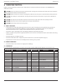
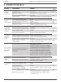
6. SERVICING THE TOOL
Regular servicing should be carried out and a comprehensive inspection performed annually or every 500,000 cycles,
whichever is sooner.
CAUTION: Never use solvents or other harsh chemicals for cleaning the non-metallic parts of the tool. These chemicals
may weaken the materials used in these parts.
CAUTION: Before maintenance, remove any dangerous substances that may have accumulated due to work processes.
CAUTION: The employer is responsible for ensuring that tool maintenance instructions are given to the appropriate
personnel.
CAUTION: The operator should not be involved in maintenance or repair of the tool unless properly trained.
CAUTION: The tool shall be examined regularly for damage and malfunction.
CAUTION: Read Safety Instructions on page 4 to 6.
6.1 DAILY SERVICING
• Daily, before use or when rst putting the tool into service, pour a few drops of clean, light lubricating oil into the
air inlet of the tool if no lubricator is tted on air supply. If the tool is in continuous use, the air hose should be
disconnected from the main air supply and the tool lubricated every two to three hours.
• Check for air leaks. If damaged, hoses and couplings should be replaced by new items.
• If there is no lter on the pressure regulator, bleed the air line to clear it of accumulated dirt or water before connecting
air hose to tool.
• Check that the nose assembly is correct.
• Check the stroke of the tool is adequate to place selected insert. (See stroke adjustment page 9).
• Inspect the drive screw in the nose assembly for wear or damage. If any, renew.
6.2 WEEKLY SERVICING
* Check for oil leaks and air leaks on air supply hose and ttings.
6.3 SERVICE KIT
For all servicing we recommend the use of the service kit (part number 74200-99990) supplied in its own plastic case.
SERVICE KIT 74200-99990
Part Number Description QTY Part Number Description QTY
07900-00618 PUSHER 1 07900-00393 14mm/15mm SPANNER 1
07900-00619 GUIDE BUSH 1 07900-00409 12mm/13mm SPANNER 1
07900-00478 Ø 3mm PIN PUNCH 1 07900-00626 11mm SPANNER 1
07900-00624 Ø 4mm PIN PUNCH 1 07900-00469 2.5mm ALLEN KEY 1
07900-00157 INTERNAL CIRCLIP PLIERS 1 07900-00351 3mm ALLEN KEY 1
07900-00161 EXTERNAL CIRCLIP PLIERS 1 07900-00224 4mm ALLEN KEY 1
07900-00625 SOFT MALLET 1 07900-00225 5mm ALLEN KEY 1
07900-00623 25mm SOCKET 1 07900-00620 12mm ALLEN KEY 1
07900-00006 SPATULA 1 07900-00456 T BAR 1
07900-00434 32mm SPANNER 1 07992-00075 MOLYKOTE 55M (100 gm TUBE) 1
07900-00621 28mm SPANNER 1 07900-00627 PLASTIC CASE 1
07900-00637 17mm SPANNER 1 07900-00632 17mm/19mm SPANNER 1
07900-00643 PUSHER KNOB 1
13
ORIGINAL INSTRUCTION ENGLISH

6.4 MAINTENANCE
Every 500,000 cycles the tool should be completely dismantled and components replaced where worn, damaged or when
recommended. All ‘O’ rings and seals should be replaced with new ones and lubricated with Molykote 55M grease before
assembling.
WARNING: Read Safety Instructions on page 4 to 6.
WARNING: The employer is responsible for ensuring that tool maintenance instructions are given to the
appropriate personnel.
WARNING: The operator should not be involved in maintenance or repair of the tool unless properly trained.
WARNING: The tool shall be examined regularly for damage and malfunction.
The airline must be disconnected before any servicing or dismantling is attempted unless specically instructed otherwise.
It is recommended that any dismantling operation be carried out in clean conditions.
Before proceeding with dismantling, empty the oil from the tool. Remove oil plug 42, oil seal washer 43, bleed screw 48 and
bleed screw washer 49 from the handle assembly and drain the oil into a suitable container.
Prior to dismantling the tool it is necessary to remove the nose assembly. For simple removal instructions see the nose
assemblies section, pages 10-13.
For total tool servicing we advise that you proceed with dismantling of sub-assemblies in the order shown below.
6.5 PNEUMATIC CYLINDER
• Remove rubber base 2.
• Place tool, base uppermost in vice tted with soft jaws.
• Using a spanner*, unscrew end plug 3. Pneumatic piston 9 should move upward under spring 11 pressure (it may be
necessary to exert hand pressure to pneumatic piston 9).
• Remove ‘O’ ring 4.
• Withdraw pneumatic piston 9.
• Remove lip seal 8 and ‘O’ ring 36.
• Hold piston rod 10 in soft vice jaws to avoid scratching rod diameter.
• Separate piston rod 10 from pneumatic piston 9 by unscrewing piston rod fastening bolt 5 using a spanner*.
• Inspect air tube 12 for damage or distortion. (Air tube is screwed internally into handle and set in position with Loctite®
222) If it is necessary to remove air tube, the base of the air tube will require warming to a temperature of 100 °C to
soften the Loctite adhesive. The air tube 12 can then be unscrewed from the handle using an Allen key*.
• Check spring 11 is not distorted or damaged.
• Assembly is in reverse order to dismantling.
6.6 ROD GUIDE
• With tool in upside down position in vice, unscrew rod guide 15 using a spanner* and T-bar*.
• Withdraw rod guide 15.
• Unscrew locknut 13 using an Allen key*, remove seal 14 and ‘O’ ring 98.
• Remove ‘O’ ring 16.
• Assembly is in reverse order to dismantling.
6.7 TRIGGER
• With tool held in vice, remove pin 26 using a pin punch*.
• Remove trigger 25, pin 22, roller 23 and push wedge 24.
• Gently push on the head of trigger rod 20 and, remove together with ‘O’ rings 7 and 21, guide 19, lip seal 18 and plug
17.
• Assembly is in reverse order to dismantling. Ensure lip of lip seal 18 is towards head of tool.
* Refers to items included in the 74200 service kit. For complete list see page 13.
Item numbers in bold refer to the General Assembly drawing and parts list (pages 18-19).
14
ENGLISH ORIGINAL INSTRUCTION

6.8 SWIVEL AIR INLET (74200-12700)
• Using an Allen key* remove screw 40 and washer 39.
• Remove swiveling inlet 38.
• Unscrew double male connector 41 from swiveling inlet 38 and remove nylon washer 33.
• Using a spanner*, remove drilled bolt 37.
• Remove two nylon washers 33 and air inlet block 35.
• Remove circlip 97 from double male connector 41 using circlip pliers and withdraw sintered lter 96.
• Assemble in reverse order of dismantling.
• Refers to items included in the 74200 service kit. For complete list see page 13.
Item numbers in bold refer to the General Assembly drawing and parts list (pages 18-19).
6.9 DIFFERENTIAL VALVE
• Using special at spanner* unscrew valve locking plug 27, withdraw and remove spring 104 and ‘O’ ring 29.
• Remove silencer 34 using a spanner* and remove nylon washer 33.
• Push valve piston 28 out from its housing together with ‘O’ rings 30, 31&32.
• Check spring 104 for distortion and renew if required.
• Assemble in reverse order of dismantling.
6.10 HEAD ASSEMBLY
• Remove nose equipment prior to commencing dismantling.
• Using spanners* remove spindle 44 and locknut 45.
• Remove return spring locknut 46 using a spanner*.
• Remove return spring 47, washer 99 and locking ring 90.
• Check return spring 47 for distortion and renew if required.
• Assemble in reverse order of dismantling.
6.11 REAR CASING
• Using an Allen key* remove screw 40 from stroke set nger 88 and lift o bridge washer 95.
• Disengage stroke set nger 88 by pushing it back against spring 89.
• Unscrew rear casing 86.
• Remove rear casing rubber band 87 if necessary.
• Extract circlip 84 using circlip pliers* and remove sintered silencer 85.
• Complete assembly in reverse order of dismantling. Locate pawl 102 in head before screwing on rear casing 86.
6.12 DISTRIBUTOR
* Using an Allen key* remove two screws 40.
* Withdraw distributor 83 together with air motor end plug 81 and ‘O’ rings 82&31 taking care not to drop ball 79 and
push rod 78.
* Using an Allen key* remove four countersunk socket head screws 58 and withdraw stroke stop 57.
* Pull out two air supply tubes 59 and four ‘O’ rings 60.
* Assemble in reverse order of dismantling.
6.13 HYDRAULIC PISTON & AIR MOTOR ASSEMBLY (74200-12610)
• Wrap adhesive tape around hydraulic piston 54 thread and move assembly backwards slowly and rmly. Using circlip
pliers* remove circlip 52 and front seal 51.
• Remove ‘O’ rings 76 and 77.
• Using two spanners* separate the hydraulic piston 54 from air motor casing 75. Shim adjustment ring 55, movement
pivot 56 and ‘O ring 101 will come out with hydraulic piston 54.
• Remove air motor assembly out of air motor casing 75, remove circlip 61 using circlip pliers*, then tap air motor casing
75 on bench to free components.
• Parts 62 to 74 can be pulled out as an assembly, taking care not to drop pin 74.
* Refers to items included in the 74200 service kit. For complete list see page 13.
Item numbers in bold refer to the General Assembly drawing and parts list (pages 18-19).
15
ORIGINAL INSTRUCTION ENGLISH

• Remove bearing 62, planet gear spindle 63, three planets 64, planet gear 65 and spacer 66.
• Using a soft mallet tap splined head of rotor 70.
• Bearing 67 and front end plate 68 will come out with stator 69 and ve rotor blades 71. (rotor 70 remains in hand).
• Place rear end plate 72 in vice with soft jaws.
• Using a pin punch* tap centre of rotor 70 to remove bearing 73. (turn rotor 70 upside down and bearing 73 will come
out).
• When assembling air motor, rear side of rotor 70 must just touch rear end plate 72 without any axial gap, (any existing
gap will disappear when bearing 73 is fully located.
• When inserting air motor into air motor casing 75 carefully align parts so that pin 74 locates in centre hole between
spin on/o ports of air motor casing 75 and rear end plate 72.
• When assembling hydraulic piston 54 onto air motor assembly, tighten parts by hand and blow air into one of the outer
ports of air motor casing 75, checking to see air motor rotates freely.
• When assembling front seal 51 ensure larger diameter faces rear of tool.
• Complete assembly in reverse order to dismantling.
CAUTION: Check the tool against daily and weekly servicing.
CAUTION: Priming is ALWAYS necessary after the tool has been dismantled and prior to operating.
* Refers to items included in the 74200 service kit. For complete list see page 13.
Item numbers in bold refer to the General Assembly drawing and parts list (pages 18-19).
16
ENGLISH ORIGINAL INSTRUCTION

6.14 MOLYKOTE 55m SAFETY DATA
Grease can be ordered as a single item, the part number is shown in the service kit page 13.
FIRST AID
SKIN: Wipe o and wash with soap and water.
INGESTION: No adverse eects are normally expected. Treat symptomatically.
EYES: Irritant but not harmful. Irrigate with water and seek medical attention.
ENNVIRONMENT
Scrape up for incinerating or disposal on approved site.
FIRE
FLASH POINT: 101 °C
Not classied as ammable.
Suitable extinguishing media: Carbon dioxide, foam, dry powder or ne water spray.
HANDLING
Plastic or rubber gloves should be worn.
STORAGE
Away from heat and oxidizing agent
6.15 PROTECTING THE ENVIRONMENT
Assure conformity with applicable disposal regulations. Dispose all waste products at an approved waste facility or site so as
not to expose personnel and the environment to hazards.
17
ORIGINAL INSTRUCTION ENGLISH

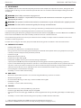
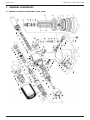
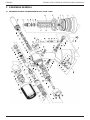
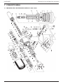
7. GENERAL ASSEMBLIES
7.1 GENERAL ASSEMBLY OF BASE TOOL 74200-12000
18
ENGLISH ORIGINAL INSTRUCTION

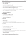
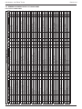
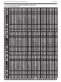
7.2 GENERAL ASSEMBLY PARTS LIST 74200-12000
Parts List for 74200-12000
74200-12000 PARTS LIST
ITEM PART N° DESCRIPTION QTY REC.
SPARES ITEM PART N° DESCRIPTION QTY REC.
SPARES ITEM PART N° DESCRIPTION QTY REC.
SPARES
01 74200-12001 HEAD & HANDLE 1 - 40 07001-00420 M4BUTTONSOCKETHDSCREW 4 4 79 74200-12079 BALL (RUBBER) 1 1
02 74200-12002 RUBBER BASE 1 1 80 73200-02022 SAFETY LABEL 1 N/1
03 74200-12003 END PLUG (SCREWED) 1 - 42 07005-01274 OIL PLUG 1 1 81 74200-12081 AIR MOTOR END PLUG 1 -
04 74200-12004 'O' RING 1 1 43 74200-12043 OIL SEAL WASHER 1 1 82 74200-12082 'O' RING 2 2
05 74200-12005 PISTON ROD FASTENING BOLT 1 - 44 74200-12044 SPINDLE 1 1 83 74200-12083 DISTRIBUTOR 1 -
06 07002-00109 M4 SHAKEPROOF WASHER 2 - 45 07555-00803 LOCK NUT 1 1
07 07003-00027 'O' RING 2 2 46 74200-12046 RETURN SPRING LOCKNUT 1 1 85 74200-12085 SINTERED SILENCER
08 74200-12008 LIP SEAL (PNEUMATIC PISTON) 1 1 47 74200-12047 RETURN SPRING 1 1 86 74200-12800 REAR CASING ASSEMBLY 1 -
09 74200-12009 PNEUMATIC PISTON 1 - 48 07001-00329 M5 BLEED SCREW 1 1 87 74200-12087 REAR CASING RUBBER BAND 1 1
10 74200-12010 PISTON ROD (INTENSIFIER) 1 - 49 07003-00033 OIL SEAL BLEED WASHER 1 1 88 74200-12088 STROKE SET FINGER 1 1
11 07555-00205 SPRING 1 1 50 07265-03021 SUSPENSION RING 1 1 89 74200-12089 SPRING 1 1
12 74200-12012 AIR SUPPLY TUBE 1 1 51 07265-02004 FRONT SEAL 1 1 90 07003-00028 LOCKING RING 2 2
13 74200-12013 LOCK NUT 1 - 52 07004-00033 CIRCLIP 1 1 91 74200-12091 NOSE CASING 1 -
14 74200-12014 SEAL 1 1 53 74200-12053 SEAL 1 1 92 74200-12092 ADAPTOR NUT (UP TO M10) 1 1
15 74200-12015 ROD GUIDE 1 - 54 74200-12054 HYDRAULIC PISTON 1 - 93 74200-12093 COLOURED LABEL 1 N/1
16 07003-00100 'O' RING 1 1 55 74200-12055 SHIM ADJUSTMENT RING 1 1 94 07900-00354 TIE ON SAFETY LABEL 1 N/1
17 74200-12017 PLUG 1 - 56 74200-12056 MOVEMENT PIVOT 1 1 95 74200-12095 BRIDGE WASHER 1 1
18 74200-12018 LIP SEAL 1 1 57 74200-12057 STROKE STOP 1 - 96 74200-12096 SINTERED FILTERED 1 1
19 74200-12019 GUIDE 1 - 58 07001-00427 M5CSKSOCKETHEADSCREW 4 4 97 74200-12097 CIRCLIP 1 1
20 74200-12020 TRIGGER ROD 1 - 59 74200-12059 PNEU. MOTOR AIR SUPPLY TUBE 2 2 98 07003-00134 'O' RING 1 1
21 07003-00315 07003-00315 'O' RING 1 1 60 74200-12060 'O' RING 4 4 99 74200-12099 WASHER 1 1
22 74200-12022 PIN 1 1 61 74200-12061 CIRCLIP 1 1 100 07007-01526 'CE' LABEL (AVDEL ITALY) 1 N/1
23 74200-12023 ROLLER 1 1 62 74200-12062 BEARING 1 - 101 74200-12121 'O' RING 1 1
24 74200-12024 PUSH WEDGE 1 - 63 74200-12063 PLANET GEAR SPINDLE 1 - 102 74200-12122 PAWL (RUBBER) 1 1
25 74200-12025 TRIGGER 1 1 64 07555-09208 PLANET 3 - 103 74200-12103 PLUG 1 1
26 74200-12026 PIN 1 1 65 74200-12065 PLANET GEAR 1 - 104 74200-12104 SPRING 1 N/1
27 74200-12027 VALVE LOCKING PLUG 1 - 66 74200-12066 SPACER 1 - 105 07900-00614 TOOL MANUAL 2 N/1
28 74200-12028 VALVE PISTON 1 - 67 07555-09206 BEARING 1 - 106 07900-00632 17/19 MM THIN SPANNER 1 N/1
29 07003-00086 'O' RING 1 1 68 07555-09210 FRONT END PLATE 1 - 107 07900-00409 12/13 MM SPANNER 1 N/1
30 07003-00040 'O' RING 1 1 69 07555-09211 STATOR 1 - 108 07900-00224 4 MM ALLEN KEY 1 N/1
31 07003-00026 'O' RING 2 2 70 74200-12070 ROTOR 1 - 109 07900-00225 5 MM ALLEN KEY 1 N/1
32 07003-00046 'O' RING 1 1 71 07555-09213 ROTOR BLADE 5 5 110 07900-00624 4 MM Ø PIN PUNCH 1 N/1
33 74200-12033 1/8" NYLON WASHER 3 4 72 07555-09214 REAR END PLATE 1 - 111 07900-00637 SPECIAL17MMFLATSPANNER 1 N/1
34 74200-12034 1/8" SILENCER 1 1 73 07555-09215 BEARING 1 - 112 07900-00469 2.5 MM ALLEN KEY
35 74200-12035 AIR INLET BLOCK 1 - 74 07555-09216 PIN 1 1 113 74200-12300 DEFLECTOR ASSEMBLY 1 N/1
36 07003-00029 'O' RING 4 4 75 74200-12075 AIR MOTOR CASING 1 - 114 74200-12700 INLET ASSEMBLY 1
37 74200-12037 DRILLED BOLT 1 - 76 07003-00305 'O' RING 1 1 115 07340-00401 SPRING 1
38 74200-12038 SWIVELLING INLET 1 - 77 07003-00306 'O' RING 5 5
39 74200-12039 WASHER 1 1 78 74200-12078 PUSH ROD 80 mm LONG 1 1
19
ORIGINAL INSTRUCTION ENGLISH

8. PRIMING
Priming is ALWAYS necessary after the tool has been dismantled and prior to operating. It may also be necessary to restore
the full stroke after considerable use, when the stroke may be reduced and fasteners are not fully placed by one operation of
the trigger.
8.1 OIL DETAILS
The recommended oil for priming is Hyspin® VG32 available in 0.5l (part number 07992-00002) or one gallon containers
(part number 07992-00006). Please see safety data below.
8.2 HYSPIN®VG 32 OIL SAFETY DATA
FIRST AID
SKIN:
Wash thoroughly with soap and water as soon as possible. Casual contact requires no immediate attention. Short term
contact requires no immediate attention.
INGESTION:
Seek medical attention immediately. DO NOT induce vomiting.
EYES:
Irrigate immediately with water for several minutes. Although NOT a primary irritant, minor irritation may occur following
contact.
FIRE
Flash point 232°C. Not classied as ammable.
Suitable extinguishing media: CO2, dry powder, foam or water fog. DO NOT use water jets.
ENVIRONMENT
WASTE DISPOSAL: Through authorized contractor to a licensed site.May be incinerated. Used product may be sent for
reclamation. SPILLAGE: Prevent entry into drains, sewers and water courses. Soak up with absorbent material.
HANDLING
Wear eye protection,impervious gloves (e.g. of PVC) and a plastic apron. Use in well ventilated area.
STORAGE
No special precautions.
8.3 PRIMING PROCEDURCE
CAUTION: Ensure that the oil is perfectly clean and free from air bubbles.
CAUTION: The tool must remain on its side throughout the priming sequence.
CAUTION: All operations should be carried out on a clean bench, with clean hands, in a clean area.
CAUTION: Care MUST be taken, at all times, to ensure that no foreign matter enters the tool, or serious damage may
result.
• Place tool on its side, oil plug 42 side up.
• Pull back stroke set nger 88 and unscrew rear casing 86 by a maximum of 5 turns from the fully ‘IN’ position.
• With an Allen key, unscrew oil plug 42 and remove with oil seal washer 43.
• Fill tool with priming oil rocking gently to expel air.
• Replace oil seal washer 43 and oil plug 42 and tighten.
• You must now bleed the tool. This operation is to ensure air bubbles are eliminated from the oil circuit.
• Ensuring oil bleed screw 48 is fully tightened unscrew by ONE TURN only, using an Allen key. Connect the tool to the air
supply and depress the trigger.
• Wait until oil appears all around oil bleed screw 48 then re-tighten. Wipe excess oil away.
• Release the trigger.
• Using an Allen Key open oil plug 42.
• Top-up with priming oil to reset level. Replace oil seal washer 43 and oil plug 42 and fully tighten.
• It is necessary to t the appropriate nose equipment and adjust the tool stroke prior to operating the tool.
Item numbers in bold refer to general assembly drawings and parts list (pages 18-19).
20
ENGLISH ORIGINAL INSTRUCTION
A página está carregando...
A página está carregando...
A página está carregando...
A página está carregando...
A página está carregando...
A página está carregando...
A página está carregando...
A página está carregando...
A página está carregando...
A página está carregando...
A página está carregando...
A página está carregando...
A página está carregando...
A página está carregando...
A página está carregando...
A página está carregando...
A página está carregando...
A página está carregando...
A página está carregando...
A página está carregando...
A página está carregando...
A página está carregando...
A página está carregando...
A página está carregando...
A página está carregando...
A página está carregando...
A página está carregando...
A página está carregando...
A página está carregando...
A página está carregando...
A página está carregando...
A página está carregando...
A página está carregando...
A página está carregando...
A página está carregando...
A página está carregando...
A página está carregando...
A página está carregando...
A página está carregando...
A página está carregando...
A página está carregando...
A página está carregando...
A página está carregando...
A página está carregando...
A página está carregando...
A página está carregando...
A página está carregando...
A página está carregando...
A página está carregando...
A página está carregando...
A página está carregando...
A página está carregando...
A página está carregando...
A página está carregando...
A página está carregando...
A página está carregando...
A página está carregando...
A página está carregando...
A página está carregando...
A página está carregando...
A página está carregando...
A página está carregando...
A página está carregando...
A página está carregando...
A página está carregando...
A página está carregando...
A página está carregando...
A página está carregando...
A página está carregando...
A página está carregando...
A página está carregando...
A página está carregando...
A página está carregando...
A página está carregando...
A página está carregando...
A página está carregando...
A página está carregando...
A página está carregando...
A página está carregando...
A página está carregando...
A página está carregando...
A página está carregando...
A página está carregando...
A página está carregando...
-
 1
1
-
 2
2
-
 3
3
-
 4
4
-
 5
5
-
 6
6
-
 7
7
-
 8
8
-
 9
9
-
 10
10
-
 11
11
-
 12
12
-
 13
13
-
 14
14
-
 15
15
-
 16
16
-
 17
17
-
 18
18
-
 19
19
-
 20
20
-
 21
21
-
 22
22
-
 23
23
-
 24
24
-
 25
25
-
 26
26
-
 27
27
-
 28
28
-
 29
29
-
 30
30
-
 31
31
-
 32
32
-
 33
33
-
 34
34
-
 35
35
-
 36
36
-
 37
37
-
 38
38
-
 39
39
-
 40
40
-
 41
41
-
 42
42
-
 43
43
-
 44
44
-
 45
45
-
 46
46
-
 47
47
-
 48
48
-
 49
49
-
 50
50
-
 51
51
-
 52
52
-
 53
53
-
 54
54
-
 55
55
-
 56
56
-
 57
57
-
 58
58
-
 59
59
-
 60
60
-
 61
61
-
 62
62
-
 63
63
-
 64
64
-
 65
65
-
 66
66
-
 67
67
-
 68
68
-
 69
69
-
 70
70
-
 71
71
-
 72
72
-
 73
73
-
 74
74
-
 75
75
-
 76
76
-
 77
77
-
 78
78
-
 79
79
-
 80
80
-
 81
81
-
 82
82
-
 83
83
-
 84
84
-
 85
85
-
 86
86
-
 87
87
-
 88
88
-
 89
89
-
 90
90
-
 91
91
-
 92
92
-
 93
93
-
 94
94
-
 95
95
-
 96
96
-
 97
97
-
 98
98
-
 99
99
-
 100
100
-
 101
101
-
 102
102
-
 103
103
-
 104
104


Stanley 74200 Blind Rivet Nut Tool Manual do usuário
- Categoria
- Ferramentas elétricas
- Tipo
- Manual do usuário