EUROSYSTEMS 08 Instruções de operação
- Categoria
- Mini lavradores
- Tipo
- Instruções de operação

MOTOZAPPA
MOTOR-HOE
MOTOBINEUSE
MOTORHACKE
MOTOAZADA
MOTORNI KULTIVATOR
MOTOKULTIVATOR
GLEBOGRYZARKA SPALINOWA
MOTOENXADA
IT Istruzioni d'uso
EN Operating instructions
FR Mode d’emploi
DE Bedienungsanleitung
ES Instrucciones de uso
SL Navodila za uporabo
HR Upute za uporabu
PL Instrukcjaobsługi
PT Instruções de utilização
Type: MZP08

11221
2A2A
2
A
3
4
1
1
5

2B2B
33
1
A
1
3
2
3
2
1

5
4455
9
1
3
4
2
4
3
5
A
1
4
8
1
231
8
4
5
7
6

66
3
7788
2
1
4
3
A
4
5
B
1
3
2 A

8/A8/A 99
1010
1
2
2
3
3
1
4
9
7
2
6
5
3
2
1
2
3
8
10
REGOLAZIONE LATERALE
LATERAL ADJUSTMENT
REGLAGE LATERAL
SEITENVERSTELLUNG DES
LENKHOLMES
REGULACIÓN LATERAL
NASTAVITEV GLEDE NA STRAN
BOČNOPODEŠAVANJE
REGULACJA BOCZNA
REGULAÇÃO LATERAL

1111
1
2
1
3
1212
1
2
3
1313
A
1
4
2
REGOLAZIONE ALTEZZA
HEIGHT ADJUSTMENT
REGLAGE EN HAUTEUR
HÖHENVERSTELLUNG DES LENKHOLMES
REGULACIÓN EN ALTURA
NASTAVITEVGLEDENAVIŠINO
PODEŠAVANJEVISINE
REGULACJAWYSOKOŚCI
REGULAÇÃO DA ALTURA

1414 21515
1
7
3 12
13
11
6
10
4
9
5
8
2
3
4
1
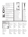
Etichetta rotazione stegola
Sticker handlebar rotation
Aufkleber Holmdrehung
Plaquetterotationmancherons
Etiquetarotaciondemanilla
Nalepkaovrtenjukrmilneročice
Oznaka za rotaciju drške za upravljanje
Naklejka obrót kierownicy
Etiquetaderotaçãodoguiador

Manufacturer
Model: xxxx-xxxxxxxxxxx
Type: xxxxx xxxx | xxxxxxxxxxxx
Nr.: xxxxxxxxx-xxxxxx
Weight: xxx kg
Date: aaaa / E
Power: x.xx kW
1
2
3
4
5
6
7
8
Leggere il manuale prima di usare la macchina -
Attenzione: rotazione fresa
Read the instructions manual before operating on the
machine - Danger tiller rotation
Lire le mode d’emploi avant l’usage - Attention: danger
rotation fraise
Lesen Sie die Gebrauchsanweisung vor der
Inbetriebnahme - Achtung: drehende Hackwerkzeuge
Antesdeprocederamontarlamàquinaleaatentamente
estas instrucciones - Atencion: la fresa gira
Preduporabonapravepreberitenavodilazauporabo–
Nevarno, vrtenje rezila
Prije uporabe naprave pročitajte upute za uporabu –
opasno,vrtnjasječiva
Przedrozpoczęciempracyzmaszynąnależyprzeczytać
instrukcjęobsługi-Niebezpieczeństwowirującenoże
Ler o manual antes de utilizar a máquina -Atenção:
rotação da fresa
Etichetta acceleratore
Plaquetteacceleration
Label accelerator
Aufkleber / Gashebel
Etiquetaacelerador
Nalepka pospeševalnika
Oznaka za ubrzavanje
Etykieta dla linki cofania
Etiquetaacelerador
Etichetta innesto Marcia avanti e Retromarcia
Forward and reverse drive label
Plaquettemarcheavantetmarchearrière
Aufkleber Vor- und Rückwärtsgang
Etiquetamarchaadelanteyatrás
Nalepkazavožnjonaprejnazaj
Oznakazavožnjunaprijed-natrag
Etykietadotyczącanapędudoprzoduidotyłu
Etiquetainserçãomovimentoparafrenteemarchaatrás
IT
1.Identicazionecostruttore
2. Modello
3.Codiceidenticativoprodotto
4. Numero di serie articolo
5. Massa
6. Anno / Mese
7.Potenzamotore
8. Tipologia prodotto
EN
1.Manufactureridentication
2. Model
3.Productidenticationcode
4. Item serial number
5. Mass
6. Year / Month
7. Motor power
8. Type of product
FR
1.Identicationduconstructeur
2.Modèle
3.Coded’identicationduproduit
4. Numéro de série de l’article
5. Masse
6. Année / Mois
7.Puissancemoteur
8. Typologie du produit
DE
1. Herstellerkennzeichnung
2. Modell
3.Produktkennzier
4. Seriennummer des Artikels
5. Gewicht
6. Jahr / Monat
7. Motorleistung
8.Produktart
ES
1.Identicaciónfabricante
2. Modelo
3.Códigodeidenticaciónproducto
4. Número de serie artículo
5.Peso
6. Año / Mes
7.Potenciamotor
8. Tipología producto
SL
1.Identikacijaproizvajalca
2. Model
3.Identikacijskakodaproizvoda
4. Serijska številka artikla
5.Teža
6. Leto / mesec
7.Močmotorja
8. Vrsta proizvoda
HR
1.Nazivproizvođača
2. Model
3.Identikacijskikôdproizvoda
4. Serijski broj artikla
5. Masa
6. Godina / mjesec
7. Snaga motora
8. Vrsta proizvoda
PL
1.Danedotycząceproducenta
2. Model
3.Kodidentykacyjnyproduktu
4.Numerseryjnyartykułu
5.Ciężar
6.Rok/miesiąc
7. Moc silnika
8. Rodzaj produktu
PT
1.Identicaçãodofabricante
2. Modelo
3.
Códigodeidenticaçãodoproduto
4. Número de série do artigo
5. Massa
6. Ano/Mês
7.Potênciadomotor
8. Tipo de produto

IT
10
Introduzione
Gentile cliente,
Leihaacquistatounanuovaattrezzatura.Laringraziamoperladuciaaccordataains.prodottieleauguriamo
un piacevole utilizzo della sua macchina.
Abbiamo creato queste istruzioni per l’uso allo scopo di assicurare, n dall’inizio, un funzionamento privo
d’inconvenienti.Seguiteattentamentequesticonsigli,avretelasoddisfazionedipossederepermoltotempouna
macchina che funziona a dovere. Le nostre macchine, prima di essere fabbricate in serie, vengono collaudate
in maniera molto rigorosa e, durante la fabbricazione vera e propria, sono sottoposte a severi controlli. Ciò
costituisce,pernoiepervoi,lamiglioregaranziachesitrattadiunprodottodiriprovataqualità.
Questa macchina è stata sottoposta a rigorosi test neutrali, nel paese d’origine, e risponde alle norme di
sicurezzainvigore.Pergarantirequesto,ènecessarioutilizzareesclusivamentericambioriginali.
L’utilizzatoreperdeognidirittodigaranziaqualoravengonoutilizzatiricambinonoriginali.
Conriservadivariazionitecnico-costruttive.Perinformazionieperordinazionidipezzidiricambiosipregadi
citare il numero di articolo e il numero di produzione.
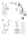
Dati per l’identicazione (Fig.1) L’etichettaconidatidellamacchinaeilnumerodimatricolaènella
parte anteriore del telaio segnata con la freccia. Nota - Nelle eventuali richieste di Assistenza Tecnica o nelle
ordinazionidellePartidiRicambio,citaresempreilnumerodimatricoladellamotozappainteressata.
Condizioni di utilizzazione - Limiti d’uso
Lamotozappa èprogettata ecostruita pereseguire operazionidizappaturadelterreno.Lamacchinadeve
lavorareesclusivamenteconattrezzieconricambioriginali.Ogniutilizzodiversodaquellosopradescrittoè
illegale; comporta, oltre al decadimento della garanzia, anche un grave pericolo per l’operatore e per le persone
esposte.
Norme di sicurezza
Attenzione: prima del montaggio e la messa in funzione leggere attentamente il libretto istruzione. Le
persone che non conoscono le norme di utilizzazione non possono usare la macchina.
1-L’usodellamacchineèvietatoaiminoridi16annieallepersonechehannoassuntoalcol,medicine
o droghe.
2-Lamacchinaèstataprogettataperessereutilizzatadaunsolooperatoreaddestrato.L’utilizzatore
dell’apparecchioèresponsabiledidanniarrecatiadaltrepersoneedalleloroproprietà;controllareche
altre persone, sopratutto i bambini stiano lontani dalla zona di lavoro (10 metri).
3 -Togliere i corpi estranei dal terreno prima di iniziare le operazioni di fresatura . Lavorare solo alla luce
delgiornooppureinpresenzadiunabuonailluminazionearticiale.
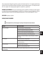
Indice
Introduzione
Condizioni di utilizzazione
Norme di sicurezza
Trasporto
Montaggio
Regolazione
Istruzioni d'uso
Manutenzione
Dati tecnici
Rumore aereo
Accessori
Guasti
Pericolograveperl’incolumità
dell’operatore e delle persone
esposte.
Istruzioni d’uso originali

IT
11
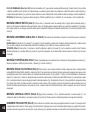
4-Nonmettereinmotolamacchinaquandosièdavantiallafresa,néavvicinarsiadessaquandoèinmoto.Tirandolacordadiavviamento
del motore, le frese e la macchina stessa devono rimanere ferme (se le frese girano intervenire sul registro di regolazione del tendi-cinghia).
5-Duranteillavoro,permaggioreprotezione,vannoindossatecalzaturerobusteepantalonilunghi.Fareattenzione,perchèilpericolodi
ferirsileditaoipiediconlamacchinainfunzione,èmoltoelevato.Camminare,noncorrere,duranteillavoro.
6 - Durante il trasporto della macchina e tutte le operazioni di manutenzione, pulitura, cambio degli attrezzi, il motore deve essere spento.
7 - Allontanarsi dalla macchina non prima di aver spento il motore.
8 - Non avviare la macchina in locali chiusi dove si possono accumulare esalazioni di carbonio.
9-AVVERTENZALabenzinaèaltamenteinammabile,conservareilcarburanteinappositirecipienti.Nonfareilpienodibenzinainlocali
chiusi né con il motore in moto. Non fumare e fare attenzione alle fuoriuscite di combustibile dal serbatoio. In caso di fuoriuscita non tentare
diavviareilmotore,maallontanarelamacchinadall’areainteressataevitandodicrearefontidiaccensionenchénonsisonodissipatii
vapori della benzina. Rimettere a posto correttamente i tappi del serbatoio e del contenitore della benzina. Non aprire il tappo della benzina
conmotoreaccesooquandoècaldo.
10 - Attenzione al tubo di scarico. Le parti vicine possono arrivare a 80°. Sostituire i silenziatori usurati o difettosi.
11- Non usare la motozappa su forti pendenze, potrebbe ribaltarsi. Sui pendii lavorare sempre trasversalmente, mai in salita o discesa ed
esercitare la massima cautela nei cambi di direzione.
12-Primadiiniziareillavoroconlamacchinaprocedereaduncontrollovisivoevericarechetuttiisistemiantinfortunistici,dicuiessaè
dotata, siano perfettamente funzionanti. E’ severamente vietato escluderli o manometterli. Sostituire i particolari danneggiati od usurati.
13 - Ogni utilizzo improprio, le riparazioni eettuate da personale non specializzato o l’impiego di ricambi non originali, comportano il
decadimento della garanzia e il declino di ogni responsabilità della ditta costruttrice.
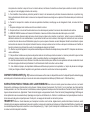
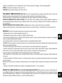
DISPOSITIVO DI SICUREZZA (Fig. 14) Tutte le motozappe sono dotate di dispositivo antinfortunistico. Detto dispositivo causa il disinnesto
automaticodellatrasmissionequandosirilascianolerelativelevedicomando(2Marciaavantie3Retromarcia).
NOTE PER IL LAVORO CON LA MOTOZAPPA A motore avviato, appoggiare i coltelli sul terreno e, tenendo saldamente la motozappa,
inlare nel terreno il timone.Abbassare la leva avanzamento (Fig. 14 part. 2) sul manubrio per far penetrare la fresa nel terreno. Sollevando
leggermentelafresamedianteilmanubrio,lamotozappasimuoveinavanti.Iltimoneduranteillavorodeverimaneresempreinlatonelterreno.
Applicazioni: Lavorazione di terreni leggeri o di media pesantezza. Lavorazione del terreno (fresatura/sminuzzamento). Dissodamento del terreno
(eliminazioneinfestanti).Incorporamentodicompostofertilizzanti,ecc.Attenzione:Lamotozappanonèadattaperlalavorazionediterreniricoperti
di cotica erbosa compatta/prato. Se ne sconsiglia inoltre l’uso sui terreni pietrosi.
TRASPORTO
Perlamovimentazioneèprevistol’usodicarrelloelevatore.Leforche,allargatealmassimoconsentito,vannoinseritenegliappositispazidelpallet.
Lamassadellamacchinaèindicatanellaetichettadellamarcatura.Tramitelaruotaditrasferimento(Fig.14part.8)èpossibileportarelamotozappa
nellaposizionediimpiegoinmodopraticoecomodo.Primaditrasportarelamacchinaspegnereilmotore.
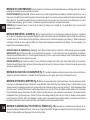
MONTAGGIO DELLA MOTOZAPPA La motozappa viene consegnata a destinazione, salvo accordi diversi, smontata e sistemata in un
adeguatoimballaggio.Percompletareilmontaggiodellamotozappaosservarelaseguenteprocedura:
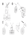
RUOTA DI TRASFERIMENTO (Fig. 2 A e 2 B) Prelevaredallascatolaimballoilsupportoruotinocompletodiruota(1)edinserirlonellasedeanteriore
deltelaio(A).Inlarelamolla(2),bloccarlaconlarondella(3)ecopiglia(4)nelforodelsupporto.Ilsupportoruotinoèinposizioneditrasportocome

IT
12
rappresentatoing.2APerpassareallaposizionedilavorotirareversodiséilsupportoruotino(1)eruotarloversodestranoaquandosiblocca.
Vedereg.2B.Lamolla,larondellaelacopigliasonoall’internodellabustaaccessori.
SPERONE (Fig. 3) Inserire lo sperone (1) in corrispondenza del foro del telaio (A). Bloccare con la rondella (2) e con la spilla a R (3) presenti
all’interno della busta accessori.
MONTAGGIO MANUBRIO (Fig. 4) P e r m o n t a r e i l m a n u b r i o ( 1 ) s u l t e l a i o d e l l a m o t o z a p p a e s e g u i r e l a s e g u e n t e p r o c e d u r a :
Nelforosuperiorefarepassarelavite(2)nelpassalo(3)alcuiinternosonogiàinseritiicavi,quindibloccarlaconildado(4).Nell’asolainferiore
utilizzareleviti(5)all’internodellemanopole(6)erondelle(7).Tuttiquestipezziperilmontaggiomanubrio,adeccezionedelpassalo(3),sono
presentinellabustaaccessoriall’internodellascatolaimballo.Perssaredenitivamenteilmanubrio(1)alrelativosupporto(8)occorreabbassare
la leva (9).
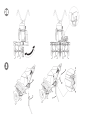
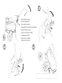
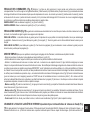
MONTAGGIO CAVI COMANDO (Fig. 5 e Fig. 6) I due cavi sono già montati sulla macchina e occorre collegarli alle rispettive leve.
MARCIA AVANTI (Fig. 5) Inserireillo(1)conilterminaleaTnell’asola(2)dellaleva(3)premontatasulmanubrio.PosizionareilterminaleaT(4)
nella sede centrale della leva (3) e dare uno strappo deciso per bloccarlo. Successivamente incastrare il terminale di plastica (5) nell’apposita sede
(A) della leva, facendo pressione verso il basso.
RETRO MARCIA (Fig. 6): Inserireillo(1)conilterminalecilindriconell’asola(2)dellaleva(3)premontatasulmanubrio.Posizionareilterminale
cilindrico(4)nellasedecentrale(A)dellaleva(3)edareunostrappodecisoperbloccarlo.Successivamenteinserireilregistrodello(5)nell’apposita
sede (B) della leva.
MONTAGGIO ACCELERATORE (Fig. 7) Illoacceleratoreègiàmontatosiasulmotorecheall’internodeldispositivoacceleratore(1).
Taledispositivovassatonelforo(A)dellastegolaconlavite(2)ebloccatoconildado(3).
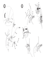
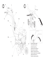
MONTAGGIO DELLE FRESE A ZAPPETTE (Fig. 8) Pulireimozzidellefreseel’alberoporta-frese;spalmareunapiccolaquantità
digrassoperfacilitareilmontaggioelafuturarimozionedellefrese.VersioneconmotoreB&S800oKohlerSH265(g.8/A):inserirelafresa(1)
badandocheicoltelliabbianol’alaturarivoltaversol’anterioredellamacchinaebloccareconduespinotti(2).Aggiungerel’allargamentofresa(3)e
ssareanchequest‘ultimoconunospinotto(2).Innebloccareildiscoproteggipiante(4)convite(5)edado(6).Ripeterelastessaoperazioneper
lafresasull’altrolato.Versioneconaltrimotori(g.8/B):lafresa(1)risultagiàmontataconnr.2vitiedaltrettantidadi,quindioccorresoloaggiungere
l’allargamento fresa (3) e bloccarlo con uno spinotto (2). Fissare il disco proteggi piante (4) con vite (5) e dado (6). Ripetere la stessa operazione per
lafresasull’altrolato.N.B.Occorremontarelospinottocomeraguratonelquadrettocentrale,cioèconilfermodiprotezionegiratonelsensodi
rotazione delle frese, in modo tale da impedire che durante il lavoro si possa aprire.
MONTAGGIO ALLARGAMENTO RIPARO FRESA (Fig. 8 A) Solopermotozappecon fresedacm.75.Prelevaredallascatola
imballo l’allargamento riparo fresa (1) con già premontate le viti (2). Montarlo facendo coincidere le viti (2) con i dadi a gabbia (3). Ripetere la stessa
operazione con l’allargamento dall’altro lato della fresa.
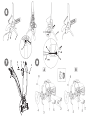
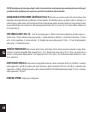
REGISTRAZIONE DEI COMANDI (Fig. 9) Attenzione! La fresa deve iniziare a girare non prima di avere agito sui rispettivi comandi.
Questosiottieneintervenendosuiregistrideili(1MA)e(2RM).Inoltrelaleva(3)checomandalamarciadizappatura,deveavviarelafresasolo

IT
13
dopoavercompiutometàdellapropriacorsa.Quandolaleva(3)dellamarciaavantielaleva(4)dellaretromarciasonoanecorsa,cioèinposizione
dilavoro,lerispettivemolledicarico(5e6)sidevonoallungaredicirca8-10mm.Seciònonavvieneèpossibileeettuareun’ulterioreregistrazione.
MARCIA AVANTI: avvitareosvitareilregistro(7)o(8)sullo(1).
RETRO MARCIA : avvitareosvitareilregistro(9)o(10)sullo(2).
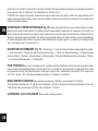
REGOLAZIONE MANUBRIO (Fig.10) Ilmanubriodellamotozappaèorientabilesialateralmentecheinaltezza.E’consigliabile,primadi
iniziarequalsiasitipodilavoro,regolareilmanubrioinbasealleproprieesigenze.
REGOLAZIONE LATERALE : l’orientamento laterale del manubrio permette all’operatore di non calpestare il terreno già zappato e non danneggiare
lavegetazione.Procederealzandolaleva(3)persbloccareilmanubrio(2)dalsupporto(1).Ruotareilmanubrio(2)dallapartedesiderataed
abbassare la leva (3) per bloccarlo.
REGOLAZIONE IN ALTEZZA: per poter sbloccare il manubrio (2) occorre ruotare le manopole (4) per allentarle. Sollevare o abbassare il manubrio
nellaposizionedesiderata(regolazionestandardl’altezzadeianchi)e,perconfermarel’esattaposizione,bloccareleduemanopole.
ISTRUZIONI D’USO D o p o l e o p e r a z i o n i d i m o n t a g g i o e r e g o l a z i o n e l a m o t o z a p p a è p r o n t a p e r l a v o r a r e .
-Regolareilmanubrioall’altezzapiùadattaallavorodaeseguire.(Vedig.10)
- P r i m a d i a v v i a r e i l m o t o r e c o n t r o l l a r e s e m p r e c h e l a m a c c h i n a s i a i n p e r f e t t e c o n d i z i o n i d i f u n z i o n a m e n t o .
-Attenzione:lamacchinavieneconsegnataconilmotoresenzaolio.Ilserbatoiohaunacapacitàdicirca0,5Kgevariempitonoallivelloindicato.
In ogni caso leggere sempre attentamente il manuale istruzioni del motore.
-Nonmodicarelataraturadelregolatoredivelocitàdirotazionedelmotoreenonfarraggiungereadessounacondizionedisopravelocità.
-IMPORTANTE:alprimoutilizzodellamacchinaèassolutamentenecessariovericarecheall’internodeltelaiosiapresentel’oliodilubricazione.
Nonavviarelamacchinasenzaavereprimafattoquestocontrollo.
- Terminato il montaggio accendere la motozappa e controllare che, portando l’acceleratore in posizione stop, il motore si spenga correttamente.
- Messa in moto del motore (Fig.14) Aprire il rubinetto del carburante (per i motori provvisti), posizionare su START la levetta dell’acceleratore posto
sulmanubrio(part.1).Seilmotoreèfreddo,azionareildispositivodistartersulcarburatore,aerrarelamanigliadiavviamento(10)edareunostrappo
energico. Avviato il motore riportare, dopo i primi scoppi, lo starter nella posizione di riposo.
-Marcia avanti (Fig. 11)Perazionarelamarciaavantiimpugnareilmanubrio(1)epremereilpulsantedisicurezza(2)cheimpediscel’innesto
accidentale delle frese. Abbassare la leva (3) per tutta la sua corsa.
-Marcia indietro (Fig. 12)Perazionarelalevaretromarciaomarciaindietro,impugnareilmanubrio(1)premereilpulsantedisicurezza(2)che
impediscel’innestoaccidentaledellefrese.Tirarelaleva(3)pertuttalasuacorsa.Questamotozappaèprogettataperridurrealminimoleemissioni
divibrazionierumore,tuttaviaèbuonanormaintervallarelavoridilungadurataconpiccolepause.
- Fine lavoro : terminato il lavoro, per arrestare il motore, portare la leva acceleratore (Fig.14 part.1) nella posizione di stop.
SOSTITUZIONE OLIO DEL CAMBIO (solo per motori/cambi a caldo) (Fig. 13) In linea di massima si dovrebbe sostituire
l’olio ogni 100 ore di lavoro. (Viscosità olio SAE 80). Cambio olio: a) Smontare lo sperone b) Allentare il tappo a vite. - c) Collocare la macchina
inposizioneinclinataeaspirarel’oliotramiteunasiringa.-d)Introdurrel’olionuovonellaquantitàdicirca0,5lt.Percontrollareilgiustolivelloè
necessario inclinare la macchina; l’olio dovrà iniziare ad uscire dal foro poco prima che la macchina (con il punto A) tocchi terra. - e) Richiudere il
foro di riempimento con il tappo a vite (1).

IT
14
IMPORTANTE! Per evitare l’inquinamento delle falde acquifere, l’olio esausto non deve essere gettato in scarichi fognari o canali idrici.
Depositi per l’olio esausto sono ubicati presso tutti i distributori di benzina, oppure in discariche autorizzate secondo le normative
comunali del Comune di residenza.
RIMESSAGGIO E MANUTENZIONE PERIODICA ( Fig. 15) Mantenere serrati tutti i dadi, i bulloni e le viti per garantire il funzionamento
dellamacchinanellecondizionidi sicurezza.Lasciarrareddarelamacchinaprimadiimmagazzinarlaecomunquenonriporlaconbenzina nel
serbatoioall’internodiunedicio,doveivaporipossonoraggiungereunaammaliberaounascintilla.Svuotareilserbatoioall’esterno.Perridurre
il pericolo di incendio mantenere il motore, il silenziatore e la zona di immagazzinamento della benzina liberi da foglie, erba e grasso in eccesso.
Controllare periodicamente il serraggio del manubrio (1) al supporto (2). Nel caso il serraggio non fosse garantito abbassare la leva (3) ed avvitare
il dado (4).
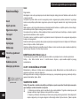
DESCRIZIONE DEI COMANDI (Fig. 14) 1. Levetta comando acceleratore a mano - 2. Leva comando avanzamento e comando di
zappatura (dispositivo antinfortunistico) - 3. Leva comando retromarcia - 4. Sperone per regolazione fresatura (unica posizione) - 5. Frese (con
allargamento) - 6. Manopola di serraggio manubrio/telaio - 7. Manubrio - 8. Ruota di trasferimento - 9. Riparo fresa - 10. Maniglia per avviamento a
strappo(dispositivoauto-avvolgente)-11.Motore–12.Levabloccaggio/sbloccaggiomanubrio-13.Supportomanubrio.
CARATTERISTICHE TECNICHE Motore:perinformazionivederelapubblicazionespecica.Trasmissione:Primariaacinghia-Secondaria
a catena. Fresa: a zappette intercambiabili per larghezza di lavoro di 50 cm e 75 cm, completa di carter di protezione e dischi proteggi piante. La
velocitàmassimadirotazionedellafresaè di140 giri/min.circa. Cambio:marciaavantiomarcia avanti+ retromarcia.Dimensioni: Lunghezza
massima 1,35 m. Larghezza massima 0,50 m - 0,75 m. Altezza 1,00 m. Dimensioni imballaggio: lunghezza 80 cm - larghezza 53 cm - altezza 69 cm.
RUMORE AEREO E VIBRAZIONI ValoredipressioneacusticaalpostodilavorosecondoEN709Leq=88,5dB(A),valored’incertezza
nellamisuraK=±0,8dB(A).ValoredipotenzaacusticasecondoEn709Lwa=96,1dB(A),valored’incertezzanellamisuraK=±0,9dB(A).
VibrazioniallestegolesecondoEN709eISO5349=5,39m/s2,valored’incertezzanellamisuraK=±0,36m/s2.
ACCESSORI : Arieggiatorepratoamolle.–Rincalzatoreadalisse.

IT
15
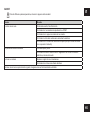
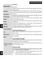
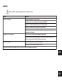
GUASTI
Primadieettuarequalsiasioperazione,staccareilcappucciodellacandela!
Guasto Rimedio
Il motore non si avvia Carburante esaurito, fare rifornimento.
Controllare che l’acceleratore sia posizionato su START.
Controllare che il cappuccio candela sia ben inserito.
Controllare lo stato della candela ed eventualmente sostituire.
Controllare che il rubinetto del carburante sia aperto (solo per i modelli di motore
incuièprevistoilrubinetto).
La potenza del motore diminuisce Filtro aria sporco, pulirlo.
Controllare che sassi o residui di terra e vegetazione non frenino la rotazione
delle frese, nel caso rimuoverli.
Le frese non ruotano Regolare i registri del cavo trasmissione.
Controllarechelefresesianossateall’albero.
Nel caso non si riesca a porre rimedio al guasto, rivolgersi ad un centro di assistenza autorizzato.

EN
16
Introduction
Dear Customer:
Thank you for your trust in purchasing our products. We wish you to enjoy using our machines.
The following working instructions have been issued to ensure you a reliable operation from the beginning. If
you carefully follow such information the machine will operate with complete satisfaction have a long service life.
Our machines are tested under the most severe conditions before being put into production and are subject to
strict continuous tests during manufacturing stages.
This unit has been tested in the country of origin by independent testing authorities in accordance with strict work
norms and safety standards.
Whenrequired,onlyoriginalsparepartsmustbeusedtomaintainguaranteedfunctionandsafetylevels.
Theoperatorforfeitsanyclaimswhichmayarise,ifthemachineshowstobettedwithcomponentsotherthan
original spare parts. Subject to changes in design and construction without notice.
Foranyquestionsorfurtherinformationandsparepartorders,weneedtobeinformedoftheunitserialnumber
printed on the side of the machine.
IDENTIFICATION DATA (Fig. 1)
The label showing the unit references and the serial number is placed in the front frame side of it and it is shown
by an arrow. Note - Always state your motor cultivator serial number when you need Technical Service or Spare
Parts.
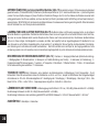
CONDITIONS OF USE AND LIMITATIONS OF USE
Thismotor-hoeisdesignedandbuilttohoetheland.Themotor-hoemustonlybeusedwithoriginalequipment
and spares. Any use other than those described above is prohibited and will involve, in addition to cancellation
of the warranty, serious risk for the operator and bystanders.
SAFETY PRECAUTIONS
Attention: Before assembly and putting into operation, please read the operating instruction carefully.
Persons not familiar with these instructions should not use the machine.
1-Personswhoarenotfamiliarwiththeoperatingmanual,aswellaschildren,adolescentsunderthe
ageof16andpersonsundertheinuenceofalcohol,drugsormedicationmustnotoperatethemower.
2 - The unit was designed in order to be used by 1 trained operator only. The person using the mower is
responsible for any accidents involving other persons or their property. When operating the machine, the
user should ensure that no others, particularly children, are standing in the area (10 mt.).
3 - Before starting to mill, remove any foreign bodies from the soil. Work only in daylight or in good
articiallight.
4 - Do not start the machine if standing in front of the rotary cutter, neither get near the machine when
List of contents
Introduction
Conditions of use
Safety measures
Instructions for operating
Transport
Assembly
Regulating
Maintenance
Technical Details
Noise
Accessories
Fault
Serious risk for operator and
bystander safety.
Translation of original user instructions

EN
17
working. If pulling the starter short rope, the rotary cutter and the machine have to standstill (if rotation is experienced, take action on the belt
stretcher control nut).
5 - During working operations, for protection purposes, it is recommended to wear technical/strong shoes and long trousers. Be careful ,
because when machine is operating the danger to be wounded in the toes or feet is really high. Walk, never run with the machine.
6-Duringthemachinetransportandallthemaintenance,cleaning,equipmentchangeoperations,theenginemustbeswitchedo.
7-Beforeleavingthemachine,pleaseswitchtheengineo.
8 - Do not switch the machine on in closed rooms/areas where you can have carbon monoxide exhalations.
9-WARNING!!Thepetrol/gasolineishighlyinammable.Storefuelonlyincontainersspecicallydesignedforthestorageofsuchmaterials.
Don’tllthetankneitherinclosedareas,norwhenengineison,don’tsmokeandbecarefultothepetrol/gasolinelossfromthetank.Incase
of leak, don’t try to switch the engine on but move the machine away from the area in order to avoid ignition source until the gasoline vapours
fade away. Re-place the tank caps and the gasoline box. Never open the cap of the fuel tank, or add fuel, while the engine is running or the
unit is hot.
10 - Keep attention to the exhaust pipe. The parts near the pipe can reach 80°C.
Replace the defective and/or worn out silencers Burn hazards !!!.
11- Don’t use the motor hoe on steep slopes: it could overturn!. On slope it is recommended to work crosswise, neither in slope nor in descent
and be vary careful during any change of direction.
12 - Before putting the machine into operations, check it visually and make sure all the accident prevention measures are working. It is
absolutely forbidden to exclude and/or to tamper with them. Replace worn or damaged elements.
13-Incasethemachineisincorrectlyused,and/ortherepairsareperformedbynon-authorizedtechnicalsta,and/orttedbyspareparts
other then original ones: any use other than that described above is prohibited and will involve the cancellation of the warranty and the refuse
all responsibility from the manufacturer.
SAFETY FEATURE (Fig. 14) All motor-hoes are provided with a safety feature which acts. The device causes the transmission to disconnect
automaticallyanytimetherespectivecontrolleversarereleased(2Forwardspeed–3Reversespeed).
NOTES ON HOW TO WORK WITH THE MOTOR-HOE Withtheenginerunning,restthetinesontheground,andrmlyholdingthe
motor-hoe, insert the spur into the soil. Lower the clutch lever on the handlebar to allow the disks to bite into the soil. The motor-hoe will move forwards
when the handlebars are used to slightly lift the disks. The spur arm must always remain in the soil during work. Uses: Light or medium textured soil
working.Soilworking(hoeing/breaking-up).Soiltillage(weeding).Ploughingincompostorfertilizers,etc.Attention:Themotor-hoeisunsuitablefor
working in soils covered by thick grass/lawns. It is also unadvisable to use the implement on stony soils.
TRANSPORT A forklift truck should be used to move the machine. The forks should be opened as far as possible and inserted into the pallet. The
weight of the machine is given on the Manufacturer’s data plate together with the other technical information. Motor-hoe can be transported to given
placebymeansoftransportwheel(Fig14part.8).Switchotheenginebeforetransportingthemachine.
HOW TO ASSEMBLE YOUR MOTOR-HOE Unless otherwise agreed, the motor-hoe is delivered disassembled and placed in a packing
case. For assembly to be completed, the step by step procedure is as follows :
TRANSFER WHEEL (Fig. 2 A and 2 B) Take from the packing box the support wheel complete with wheel (1) and insert it in the front seat of the

EN
18
frame (A). Fit the spring (2) and secure it with the washer (3) and the cotter pin (4) into the housing hole. The wheel support is in the transport position
asshowninFig.2A.Toshifttoworkpositionpullittowardsthewheelsupport(1)andturnittotherightuntilitstops.Seeg.2B.Thespring,washer
and cotter pin can be found inside the bag accessories.
SPUR (Fig. 3) Insertthespur(1)incorrespondenceoftheholeoftheframe(A).Securewithwasher(2)andwiththeRpin(3)youcanndinthe
accessories bag.
HANDLEBAR ASSEMBLY ( Fig. 4) : To assemble the handlebar (1) on the tiller frame, perform the following steps:
In the upper hole to pass the screw (2) in the grommet (3) with already entered the control cables and then secure it with the nut (4). Use the lower
slot screws (5) inside of the knobs (6) and washers ( 7). All these pieces for mounting handlebar with the exception of the grommet (3), are present in
theenvelopeaccessoriesinsidethepackagingbox.Totdenitivelythehandlebar(1)tothecorrespondingsupport(8)youneedtolowerthelever
(9).
CONTROL CABLES ASSEMBLY (Fig. 5 - Fig. 6): The two cables are already installed on the unit and must be connected to the
corresponding levers.
FORWARD (Fig. 5) Insertthewire(1)withtheterminalT-slot(2)ofthelever(3)pre-mountedonthehandlebar.Placethecylindricalterminal(4)into
theseatofthelever(3)andgivearmtugtolockit.Thenpinchthewireadjuster(5)intotheseat(A)ofthelever,bydoingdownwardpressure.
REVERSE (Fig. 6): Insertthewire(1)withthecylindricalterminalintotheslot(2)ofthelever(3)pre-assembledonthehandlebar.Placethecylindrical
terminal(4)intothecentralseat(A)ofthelever(3)andgivearmtugtolockit.Theninsertthelogthread(5)intoplace(B)ofthelever.
THROTTLE ASSEMBLY (Fig. 7) The throttle wire is already mounted both on the engine inside the throttle device (1). Such a device is
fastened in the hole (A) of the handlebar with the screw (2) and locked with the nut (3).
ASSEMBLY THE HOE TILLER (Fig. 8) Clean the tiller hubs and the tiller-shaft; apply some grease to make mounting and tiller removal
easierinthefuture.B&S800/KohlerSH265enginemodel(g.8/A):inserttherotavator(1)makingattentionthekniveshavethesharpeningside
turnedtothefrontpartofthemachineandblocktherotavatorwithtwopins(2)assemblingtheextra-widetines(3)andxitwith1pinaswell(2).Then
blockthetreesaverdisk(4)with1screw(5)and1nut(6).Repeatthesameoperationfortherotavatorontheothermachineside.Otherengines(g.
8/B): the rotavator (1) is already assembled with nr. 2 screws and the same number of nuts so you only need to assemble the extra-wide tines (3)
andblockitwithpin(2)andxthetreesaverdisk(4)withscrew(5)andnut(6).Repeatthesameoperationfortherotavatorontheothermachine
side.N.B.=pleasenoteitisnecessarytoassemblethepinasshowninthepictureplacedinthecentreofthepage,i.e.,withtheprotectionstopping
device turned in the same direction the rotavators are turning, in order to avoid the pin to open during working operations.
ASSEMBLY OF THE TINES GUARD (Fig. 8 A) Only tillers with cm. 75 rotavator. Remove the packing box enlargement widening tines
guard (1) with pre-assembled screws (2). Mount it by aligning the screws (2) with cage nuts (3). Repeat the same operation with the widening tines
of the other side of the rotavator.

EN
19
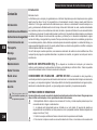
CONTROL ADJUSTMENT : (Fig. 9) Attention! The rotavator has to start working only after having operated on the control levers. Such
operation can be performed by acting on the handlebar cables (1 Forward speed) 2 (Reverse speed) register. Furthermore the lever controlling the
digging speed (3) should start the rotavator only after having performed half its way. When the lever (3) and the lever (4) are held toghether, i.e. on
working operation , the belt stretcher load-spring for forward speed ( 5e 6 ) should be extended for about 8-10 mm. If the handlebar register is not
enough to obtain any conditions , please go on another adjustment.
FORWARD: screw or unscrew the adjuster (7) or (8) on the wire (1).
REVERSE: screw or unscrew the adjuster (9) or (10) on the wire (2).
HANDLEBAR ADJUSTMENT (Fig. 10) The motor-hoe handlebar can be both side and height adjusted. Before starting any work it is a
goodstandardoperatingproceduretoadjustthehandlebartotheoperator’srequirementssothatthemachinecouldbeeasilyhandled.
LATERAL ADJUSTMENT : The lateralinclination ofthehandlebarallowstheoperatortokeepo thecultivated groundandnottosquashthe
vegetation around. Go on raising the lever (3) to unlock the handlebar (2) from the support (1). Turn the handlebar to the desired part and lower
the lever (3) to lock it.
HEIGHT ADJUSTMENT : in order to unlock the handlebar (2) you need to turn the handles (4) to loosen them .
Raise or lower the handlebar in the desired position ( the standard adjustment is at the sides height/level). To settle the right position, tighten the 2
handles.
INSTRUCTIONS Following the assembly & adjustment operations the motor-hoe is ready to start working.
-Adjustthehandlebartotherequestedposition/height(seeg.10).
- Before switching the engine on, carefully check if the motor-hoe is in perfect good repair.
-Attention:themotor-hoeisdeliveredwithouttheoilintotheengine.Thetankhasgotacapacityforabout0,5kg.andshouldbelledinuptothe
indicated level. In any case the operator should always carefully read the engine instructions manual.
- Do not change the calibration of the speeds control rotation device of the engine in order not to over-speed it.
IMPORTANT:attherstuseofthemachineitisabsolutelynecessarytoverifythatinsidethechassistobepresentthelubricationoil.Donostart
the unit/machine on before having done such control.
-Whenyouhavenishedtheassembly,switchthemotor-hoeonandcheck,bringingtheacceleratortostopposition,theenginetoshutcompletely
down.
-Howtoswitchtheengineon(Fig.14):Openthefuelcap(fortheengineequippedlikethis),pushtoSTARTtheacceleratorleveronthehandlebar
(1). If the engine is cold, operate the starter device on the carburettor, bring the starter handle (10) and pull energetically.
When the engine is on, after some bursts/bangs, put the starter again at rest position.
- Forward speed (g.11): Grip the handlebars (1) and press the safety device (2) which is preventing the accidental tines connection. Lower the
forward lever (3) all its way long.
- Reverse speed (Fig. 12):Gripthehandlebars(1)andpressthesafetydevice(2)whichispreventingtheaccidentaltinesconnection.Pullthe
reverse lever (3) all its way long.
The present machine has been projected in order to lower to the minimum the vibrations and noise levels. Anyhow we can advise you to stop working
any now and then in case you would need to perform/work for a long period.
- Stop working operation :Tostopthework,switchtheengineo,bringtheacceleratorlever(Fig.14part1)intostopposition.

EN
20
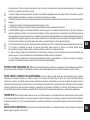
GEAR BOX OIL CHANGE (only when engine/gear box is working using a hot device) (Fig. 13) As a general rule the
oil should be changed after every 100 work hours (oil viscosity SAE 80). To change oil: a) Remove the spur. b) Unscrew the screw cap. - c) Tilt the
machineandintaketheoilthroughasyringe.-d)Pourinabout0,5l.ofnewoil.Tiltthemachinetocheckthatleveliscorrect.Theoilshouldbeginto
owfromtheholejustbeforethemachinetouchestheground(withpointA)-e)Replacethellerscrewcap(1).
ATTENTION! The used oil must not be drained into the sewer system or waterworks. In order to prevent any pollution to the water-table.
Most garages have used oil deposits, or use the authorized deposits according to your local authority regulations.
GARAGING AND SCHEDULED MAINTENANCE (Fig. 15) Keep attention that all the nuts, screws and bolts are tightened in order
to guarantee a good machine working on safety conditions. Leave the machine to cool before garaging anyhow don’t room it if the tank still contains
somefuelasthevapourscouldreachsomeblazesorsparks.Thefueltankistobedrainedoutdoorsonly.Tolowertheredanger,keeptheengine,
thesilencerandthefuelareafreefromleaves,grassorgreasysubstances.Periodicallycheckthetightnessofthehandlebar(1)tothesupport(2).
If the tightening is not guaranteed, please lower the lever (3) and tighten the nut (4).
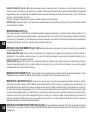
DESCRIPTION OF CONTROLS (Fig. 14) 1. Throttle lever - 2. Hoeing gear control lever (safety feature) - 3. Reversing lever - 4. Tilling
adjustment spur (single position) - 5. Cultivator blade (with enlargement) - 6. Knobs handlebar/frame - 7. Handlebar - 8. Transport Wheel - 9. Hoe
shield-10.Pull-outhandle(self-windingdevice)11.Motor–12.Lock/releaseleverforhandlebar–13.Handlebarsupport
TECHNICAL SPECIFICATION Engine:consultthespecicpublicationforinformation.Transmission:primarybybelt,secondarybychain.
Tiller:ttedwithinterchangeablehoes.Workingwidth50cmand75cm.Thehighestspeedofrotationofthetillerisabout140R.P.M.Transmission:
singlespeedorsinglespeed+reversespeed.Maxlength:1,35m.Maxwidth:0,50-0,75m.Height:1,00m.Packagedimensions:long80cm-wide
53 cm - high 69 cm.
NOISE AND VIBRATION LEVEL MeasuredsoundpressurelevelwithEn709,Leq=88,5dB(A),withauncertaintyvalueK=±0,8dB(A).
MeasuredsoundpowerlevelwithEn709,Lwa=96,1dB(A),withauncertaintyvalueK=±0,9dB(A).
HandlebarvibrationincompliancewithEN709andISO5349.Levelmaxdetected=5,39m/s2,uncertaintyvalueK=±0,36m/s2.
ACCESSORIES: Ridging plough and De-Thatcher.
A página está carregando...
A página está carregando...
A página está carregando...
A página está carregando...
A página está carregando...
A página está carregando...
A página está carregando...
A página está carregando...
A página está carregando...
A página está carregando...
A página está carregando...
A página está carregando...
A página está carregando...
A página está carregando...
A página está carregando...
A página está carregando...
A página está carregando...
A página está carregando...
A página está carregando...
A página está carregando...
A página está carregando...
A página está carregando...
A página está carregando...
A página está carregando...
A página está carregando...
A página está carregando...
A página está carregando...
A página está carregando...
A página está carregando...
A página está carregando...
A página está carregando...
A página está carregando...
A página está carregando...
A página está carregando...
A página está carregando...
A página está carregando...
A página está carregando...
A página está carregando...
A página está carregando...
A página está carregando...
A página está carregando...
A página está carregando...
A página está carregando...
A página está carregando...
-
 1
1
-
 2
2
-
 3
3
-
 4
4
-
 5
5
-
 6
6
-
 7
7
-
 8
8
-
 9
9
-
 10
10
-
 11
11
-
 12
12
-
 13
13
-
 14
14
-
 15
15
-
 16
16
-
 17
17
-
 18
18
-
 19
19
-
 20
20
-
 21
21
-
 22
22
-
 23
23
-
 24
24
-
 25
25
-
 26
26
-
 27
27
-
 28
28
-
 29
29
-
 30
30
-
 31
31
-
 32
32
-
 33
33
-
 34
34
-
 35
35
-
 36
36
-
 37
37
-
 38
38
-
 39
39
-
 40
40
-
 41
41
-
 42
42
-
 43
43
-
 44
44
-
 45
45
-
 46
46
-
 47
47
-
 48
48
-
 49
49
-
 50
50
-
 51
51
-
 52
52
-
 53
53
-
 54
54
-
 55
55
-
 56
56
-
 57
57
-
 58
58
-
 59
59
-
 60
60
-
 61
61
-
 62
62
-
 63
63
-
 64
64


EUROSYSTEMS 08 Instruções de operação
- Categoria
- Mini lavradores
- Tipo
- Instruções de operação
em outras línguas
- español: EUROSYSTEMS 08 Instrucciones de operación
- français: EUROSYSTEMS 08 Mode d'emploi
- italiano: EUROSYSTEMS 08 Istruzioni per l'uso
- polski: EUROSYSTEMS 08 Instrukcja obsługi